Home | Projects | Notes > ARM Cortex-M3/M4 Processor > Bit Banding
Bit Banding
Bit Banding
Bit banding is the capability to address a single bit of a memory address.
This feature is optional. i.e., MCU manufacturer may or may not support it. Consult the reference manual!
Bit banding provides atomic operations (i.e. will not be interrupted) to bit data.
To access a word (4 byte), use
ldr,str.To access a half-word (2 byte), use
ldrh,strh.To access a byte, use
ldrb,strb.To access a bit, use bit banding.
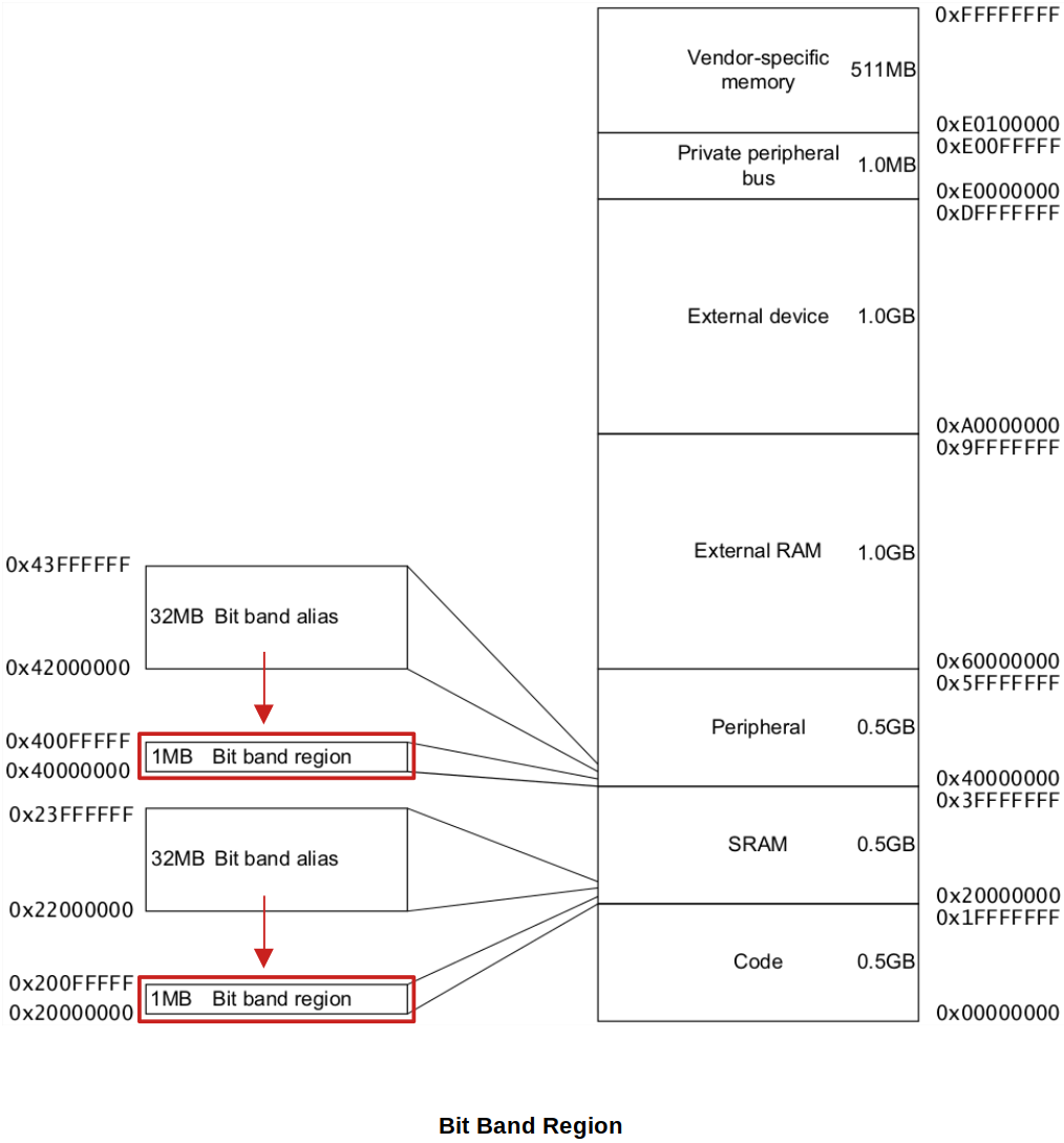
xxxxxxxxxx41@ To set the bit-0 of the byte r1 points to (without bit banding):2ldrb r0, [r1] @ load a byte3orr r0, r0, #0x01 @ set bit-04strb r0, [r1] @ store the result backxxxxxxxxxx21@ To set the bit-0 of the byte r1 points to using bit banding:2ldrb r0, [<alias_address>]These bit-addressable region is called the "Bit band region", and each bit in the bit band region can be addressed by using the "Bit band alias" address. See the following diagram. Here, the bit band feature is supported only within the Peripheral region and SRAM region.
(Think about the relationship between 1MB and 32 MB.)

Example of "Bit" to "Bit band alias" mapping:
xxxxxxxxxx91Bit-band Region Alias address2------------------ -----------------30x20000000 bit[0] <------------------- 0x22000000 bit[0]40x20000000 bit[1] <------------------- 0x22000004 bit[0]50x20000000 bit[2] <------------------- 0x22000008 bit[0]6... ...70x20000000 bit[31] <------------------ 0x2200007C bit[0]80x20000004 bit[0] <------------------- 0x22000080 bit[0]90x20000004 bit[1] <------------------- 0x22000084 bit[0]
Calculation of Bit Band Alias Address
Generic formula:
Alias address = alias_base + (32 * (bit_band_memory_addr - bit_band_base)) + bit * 4
What is the alias address of the 7th bit position of the memory location 0x20000200?
Bit Banding - Demonstration
Program to modify the 7th bit position of the memory location 0x20000200 with/without using bit banding.
xxxxxxxxxx2812345678910int main(void)11{12uint8_t *ptr = (uint8_t *)0x20000200;1314*ptr = 0xff;1516// 1. without using bit banding17*ptr &= ~(1 << 7); // clearing 7th bit position of a byte in 0x200002001819// reset the value20*ptr = 0xff;2122// 2. using bit banding23uint8_t *alias_addr = (uint8_t *)(ALIAS_BASE + (32 * (0x20000200 - BITBAND_BASE)) + 7 * 4);24*alias_addr = 0; // clearing 7th bit position of a byte in 0x200002002526/* Loop forever */27for(;;);28}Without using bit banding generates this many assembly instructions:
xxxxxxxxxx7117 *ptr &= ~(1 << 7); // clearing 7th bit position of a byte in 0x200002002080001f8: 7b 68 ldr r3, [r7, #4]3080001fa: 1b 78 ldrb r3, [r3, #0]4080001fc: 03 f0 7f 03 and.w r3, r3, #127 ; 0x7f508000200: da b2 uxtb r2, r3608000202: 7b 68 ldr r3, [r7, #4]708000204: 1a 70 strb r2, [r3, #0]Using bit banding generates much less instructions:
xxxxxxxxxx4124 *alias_addr = 0; // clearing 7th bit position of a byte in 0x20000200208000210: 3b 68 ldr r3, [r7, #0]308000212: 00 22 movs r2, #0408000214: 1a 70 strb r2, [r3, #0]
References
Nayak, K. (2022). Embedded Systems Programming on ARM Cortex-M3/M4 Processor [Video file]. Retrieved from https://www.udemy.com/course/embedded-system-programming-on-arm-cortex-m3m4/