Home | Projects | Notes > ARM Cortex-M3/M4 Processor > Embedded Systems Basics
Embedded Systems Basics
Analyzing Embedded C Program Requires
Anatomy of the microcontroller
Identifying code and data parts of the program
Code memory and data memory of the MCU
Disassembly feature of the IDE
Analyzing the executable (.elf) using GNU tools (e.g., objdump and size)
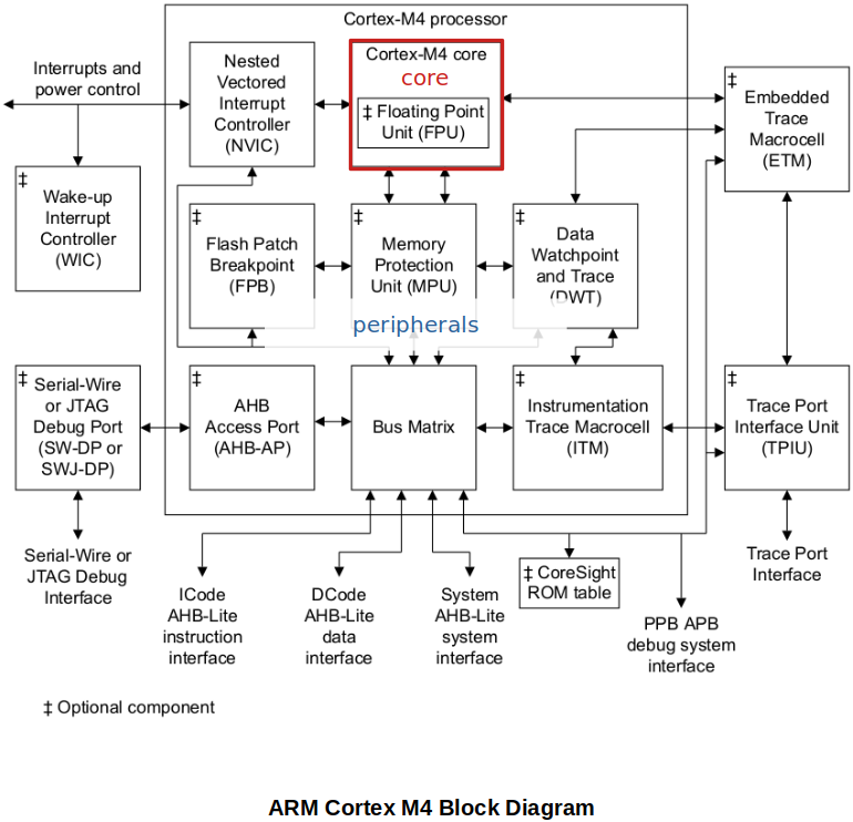
Processor (CPU) vs. Core
Processor (CPU) = Core + Processor specific peripherals
Core
Basic computational engine of the processor
Consists of ALU where data computation takes place and result will be generated
Consists of Address Generation Unit (ADU)
Consists of hardware multiplication and division engine
Has the logic to decode and execute an instruction
Has multiple registers to store and manipulate data
Has pipeline engine to boost the instruction execution
A processor may contain multiple cores depending on the design
Processor specific peripherals (e.g., NVIC, FPB, MPU, DWT, etc.)
Types of peripherals may vary depending on the design
Microcontroller
Microcontroller (MCU,
A typical microcontroller includes on a single chip:
Processor(s)
Volatile/non-volatile memory(s)
SRAM, FLASH, ROM, EEPROM, etc.
Input/output pins
Peripherals
ADC, DAC, TIMERS, UART, USB, etc.
Clock
Bus interfaces
etc.
In the case of STM32F40xxx microcontroller, the ARM Cortex-M4 processor acts as the master. It communicates with various slaves (i.e., peripherals) via bus interfaces.

Anatomy of a Typical Microcontroller
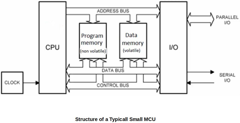
CPU - Executes instructions
Program (code) memory (non-volatile) - Stores instructions and constant data of your program.
ROM (Read-Only Memory)
MPROM (Mask Programmable Read-Only Memory)
Once written, cannot be rewritten
EPROM (Ultraviolet Erasable Programmable ROM)
Can be rewritten, but the process is very cumbersome. Take the chip out of the circuit, put it under the ultraviolet machine to erase the memory, and then program it again! Therefore, EPROMs are not used for memories inside MUCs anymore.
EEPROM (Electrically Erasable Programmable ROM)
Easier of the three to rewrite. Erased by a certain electric voltage. Still used in some of the MCUs that are produced today.
OTP (One Time Programmable)
Flash (Electrically Erasable Programmable ROM)
Popular in MCUs. Fabrication process is easier that that of EEPROM's. Flash memories are faster and cheaper than EEPROMs.
FRAM (Ferroelectric Random Access Memory)
Much faster than Flash memories but also more expensive. Some of the TI MCU uses FRAM as a code memory in stead of Flash memory.
Data memory (volatile) - Stores the data used in the program. Mainly consumed during the run-time and can be used as a scratch pad to temporarily store the data or so. (e.g., SRAM)
Bus interfaces - A group of wires through which information (i.e., data, addresses) is transferred (e.g., address but, data bus, control but, etc.)
I/O interfaces - Allows the MCU to communicate with the outside world (e.g., serial I/O, parallel I/O, etc.)
ELF File
To analyze
.elffiles a GNU toolarm-none-eabi-objdumpis needed. Install the tool first using the following command:xxxxxxxxxx11$ sudo apt install binutils-arm-none-eabiThen go to the project directory
.elffile is locatedxxxxxxxxxx11$ arm-none-eabi-objdump -h <project_name>.elfELF file has many sections:
.textsection contains the code or all the instructions of your program..rodatasection contains all the read-only data of your program..datasection contains all the data of your program.
Field names
VMAandLMA:LMA: Load Memory Address (Source in FLASH) - Shows where the section is currently loaded.VMA: Virtual Memory Address (Destination in SRAM) - Shows where (RAM address) the section should finally be copied to. This copying is done by the startup code of your project.
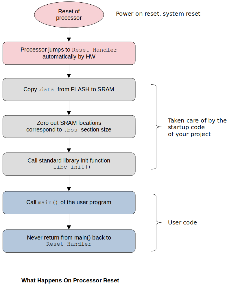
When the IDE loads the
.elffile into FLASH memory,.dataand.rodatasections as well as.textsection also get stored in the FLASH memory. Then the startup code of your project copies.datasection from FLASH to SRAM. The address information can be found in the.elffile!The following diagram shows what happens on the processor reset. The first destination of the processor (by hardware) is
Reset_Handlerof the startup code.
Summary:
You can identify the data and code section of your program. Here, code actually means the opcodes, the machine codes. The code will get stored in the Flash memory (i.e., program memory). The data of your program will be copied from the Flash memory to the SRAM (i.e., data memory) by the startup code upon the processor reset.
Startup code is a part of your project and is added automatically by the IDE when you create a project.
Disassembly
We can use objdump tool to disassemble the machine code generated.
.elffileDisassembly is very helpful when you need to do the instruction level debugging. And if you want to understand how exactly the control is passed from on part of the program to another, and if you want to check whether there is any room for optimization at all.
IDE supporting disassembly feature is essentially running the objdump tool on the
.elffile behind the scenes.In our case, the processor and architecture information is as follows:
Processor: ARM Cortex M4
Processor architecture: ARMv7E-M
Instruction Set Architecture (ISA): Thumb-2 instruction set (16/32 bits instruction encoding)
Example:
To see the disassembly using the objdump tool:
xxxxxxxxxx11$ arm-none-eabi-objdump -d <project_name>.elfxxxxxxxxxx221...208000290 <main>:38000290: b580 push {r7, lr}48000292: af00 add r7, sp, #058000294: 4b06 ldr r3, [pc, #24] ; (80002b0 <main+0x20>)68000296: 681a ldr r2, [r3, #0]78000298: 4b06 ldr r3, [pc, #24] ; (80002b4 <main+0x24>)8800029a: 681b ldr r3, [r3, #0]9800029c: 4413 add r3, r210800029e: 4a06 ldr r2, [pc, #24] ; (80002b8 <main+0x28>)1180002a0: 6013 str r3, [r2, #0]1280002a2: 4b05 ldr r3, [pc, #20] ; (80002b8 <main+0x28>)1380002a4: 681b ldr r3, [r3, #0]1480002a6: 4619 mov r1, r31580002a8: 4804 ldr r0, [pc, #16] ; (80002bc <main+0x2c>)1680002aa: f000 f905 bl 80004b8 <iprintf> @ 32-bit instruction1780002ae: e7fe b.n 80002ae <main+0x1e> @ 16-bit thumb instruction1880002b0: 20000000 .word 0x200000001980002b4: 20000004 .word 0x200000042080002b8: 20000088 .word 0x200000882180002bc: 080013dc .word 0x080013dc22...To see the disassembly using the CubeIDE, Window
xxxxxxxxxx241Address Opcode Assembly level instruction2--------- ------ -----------------------------------------------3...4main:508000291: b5 00 push {r7, lr}608000293: af 06 add r7, sp, #0733 result = g_data1 + g_data2;808000294: 06 4b ldr r3, [pc, #24] ; (0x80002b0 <main+32>)908000296: 1a 68 ldr r2, [r3, #0]1008000298: 06 4b ldr r3, [pc, #24] ; (0x80002b4 <main+36>)110800029a: 1b 68 ldr r3, [r3, #0]120800029c: 13 44 add r3, r2130800029e: 06 4a ldr r2, [pc, #24] ; (0x80002b8 <main+40>)14080002a0: 13 60 str r3, [r2, #0]1534 printf("Result = %d\n", result);16080002a2: 05 4b ldr r3, [pc, #20] ; (0x80002b8 <main+40>)17080002a4: 1b 68 ldr r3, [r3, #0]18080002a6: 19 46 mov r1, r319080002a8: 04 48 ldr r0, [pc, #16] ; (0x80002bc <main+44>)20080002aa: 00 f0 05 f9 bl 0x80004b8 <printf>2137 for(;;);22080002ae: fe e7 b.n 0x80002ae <main+30>23080002b0: 00 00 movs r0, r024...In the CubeIDE, Instruction Stepping Mode helps going through the instruction by instruction.
References
Nayak, K. (2022). Embedded Systems Programming on ARM Cortex-M3/M4 Processor [Video file]. Retrieved from https://www.udemy.com/course/embedded-system-programming-on-arm-cortex-m3m4/