Home | Projects | Notes > Computer Architecture & Organization > ARM Addressing Modes
ARM Addressing Modes
ARM Addressing Modes
Addressing mode is the manner in which operand are specified in the instruction.
3 things we want to figure out when discussing addressing modes.
What is the effective address?
Where is the data (i.e., operand)?
Is it somewhere in the CPU or in the memory?
Are there any side effects (e.g., register value updates, etc.)?
ARM Addressing Mode Summary
xxxxxxxxxx521Addressing Mode Effective Address Data Location / Example2 Side Effects3================= ===================== =================== =================4Literal None Instruction MOV r0, #125(Immediate)6----------------- --------------------- ------------------- -----------------7Direct Contained in the Main memory LDR r0, address8(Absolute) instruction 9[!] Note: ARM assembly does not support Direct Addressing mode.10----------------- --------------------- ------------------- -----------------11Indirect Contained in the Main memory LDR r0, [r1]12(Register referenced register (r1 does't change)13Indirect) 14----------------- --------------------- ------------------- -----------------15Indirect with Calculated by Main memory LDR r0, [r1, #4]16Offset adding the offset LDR r0, [r1, r2]17 to the value stored (r1 doesn't change)18 in the referenced19 register20 The offset can be:21 - Literal22 - Contents of 23 another register24----------------- --------------------- ------------------- -----------------25Auto-indexing Calculated by Main memory / LDR r0, [r1, #8]!26Pre-indexed adding the offset Index register is LDR r0, [r1, r2]!27 to the value stored updated BEFORE the (r1 gets updated)28 in the referenced memory access 29 register (This has to be30 The offset can be: verified! Effective31 - Literal addr is calculated32 - Contents of before memory access33 another register for sure, but the34 index register is 35 said to be updated36 after the memory 37 access according 38 to the text.)39----------------- --------------------- ------------------- -----------------40Auto-indexing Contained in the Main memory / LDR r0, [r1], #841Post-indexed referenced register Index register is LDR r0, [r1], r242 updated AFTER the (r1 gets updated)43 memory access44----------------- --------------------- ------------------- -----------------45Program Counter Calculated by Main memory B [PC, #32]46Relative adding the offset to B [PC, r0]47 the Program Counter48 The offset can be:49 - Literal50 - Contents of 51 another register52----------------- --------------------- ------------------- -----------------1. Literal (or Immediate) Addressing
There is no effective address.
The data is part of the instruction. In ARM it is
#n.This is also called immediate adressing because no additional memory access is necessary to get the data.
Examples
xxxxxxxxxx91MOV r0, #12 @ Default is decimal2MOV r1, #0xFF3MOV r1, #FFH @ #FFH, #0xFF both indicate the literal is in hex4CMP r0, #45CMP r0, #2_0100 @ Prefix '2_' denotes binary numbers6ADD r1, r2, #878@ Use single quote for character literals: 'A'9@ Use double quotes for character literals: "Hello world!"The literal has to be the LAST operand in the instruction.
ARM's way of treating literal operands
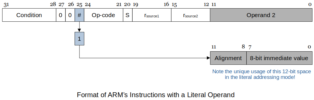
A
1in bit 25 of the instruction identifies the instruction has literal addressing.Literals are 8-bits that can be scaled by a power of 2. (A unique feature of the ARM.)
This applies only to the literal addressing. (Literal addressing and literal offsets are two different things!)
Literal offsets will use the whole 12-bit space to represent numbers in two's complement notation. (See the Literal Offset section below.)
The way the 12-bit Operand 2 is decoded:
xxxxxxxxxx141Alginment 8-bit immediate value Results2========= ===================== =======================================30000 Range 0 to 255 0 to 2554--------- --------------------- ---------------------------------------50001 Range 0 to 255 Shift left the immediate value6two times (Effect is *4)7[!] Note: The number of shift is TWICE8the alignment value!9--------- --------------------- ---------------------------------------101000 Range 0 to 255 Shift left the immediate value11eight times (Effect is *16)12[!] Note: The number of shift is TWICE13the alignment value!14--------- --------------------- ---------------------------------------Due to the size limitation of the "immediate value" you can't directly load a literal that does not fit into 8 bits.
If you want to load
0xFFFFinto a register, do the following:xxxxxxxxxx31MOV r0, #0xFF @ RTL: [r0] ← 0x000000FF (do this least significant 8 bits first)2ORR r0, #0xFF00 @ RTL: [r0] ← 0x0000FFFF (and then do the rest)3@ ORR does bitwise OR operationThe best approach is to specify the value you want and let the assembler figure it out. You can do the following instead.
xxxxxxxxxx11MOV r0, #0xFFFFFor the ARM, if you get "Assembler Error: invalid constant (123) after fixup." by writing,
xxxxxxxxxx11MOV r0, #0x123this means the assembler cannot handle this as a literal and you will have to define your own constant in the data section. For example: (ARM's unique way of solving this problem)
xxxxxxxxxx71LDR r1, =c12345678 @ Get the address for the long constant into r12LDR r0, [r1] @ Load the constant into r034.data56.balign 47c12345678: .word 12345678Some assemblers, when recognizng a long constants, might set-up a memory location and set it to the value and use PC offset addressing to work around it.
2. Direct (or Absolute) Addressing
The effective address is contained in the instruction.
The operand (or data) is in the main memory.
ARM does NOT directly support this addressing mode.
3. Indirect (or Register Indirect) Addressing
All computers support some form of register indirect addressing. This is also called:
Indexed
Pointer-based
The effective address is contained in the base register which is contained in the instruction.
Examples
xxxxxxxxxx81LDR r1, [r0] @ Load r1 with the contents of the memory location pointed by r02@ RTL: [r1] ← [[r0]]34STR r1, [r0] @ Store the contents of r1 in the memory location pointed by r05@ RTL: [[r0]] ← [r1]67ADD r0, r0, #4 @ Add 4 to the contents of r48@ i.e., increment the pointer by one wordCode to determine the length of a string:
xxxxxxxxxx161MOV r2, #-1 @ Do not count the terminating null char in string length2LDR r0, =str1 @ Assembler uses the = to get the address of 'str1'34loop:5LDR r1, [r0] @ This is the register indirect addressing6AND r0, #0xFF @ Mask off all but LSB (Least Significant Byte)7ADD r0, r0, #1 @ r0 is the pointer to the string8ADD r2, r2, #1 @ r2 is the character counter9CMP r1, #0 @ When reached the terminating null char, end the loop10BNE loop11MOV r0, r2 @ Put length into r0 to print results1213.data1415.balign 416str1: .asciz "This is a long string that end with the null character."
4. Register Indirect Addressing with Offset
The effective address is calculated by,
(The value stored in the referenced register) + (offset)therefore, also called as base plus displacement addressing.In this case the literal is true 12-bit number not the 8-bit number with a 4-bit offset.
The 12-bit contents are in two's complement; both positive and negative numbers are allowed.
0 ~ 4096(unsigned)-2048 ~ 2047(signed)
The value stored in the referenced register is NOT CHANGED.
The address calculation is done BEFORE the memory access is performed.
Examples
xxxxxxxxxx131LDR r0, [r1, #32] @ Load r0 with the contents of memory location pointed2@ by r1+32. (r1 value does not change!)3@ -----4@ effective address5@6@ RTL: [r0] ← [[r1] + 32]78LDR r2, [r0, r1] @ Load r2 with the contents of memory location pointed9@ by r0+r1. (r0 value does not change!)10@ -----11@ effective address12@13@ RTL: [r2] ← [[r0] + [r1]]You can specify the offset as a second register so that you can use a dynamic offset that can be modified at runtime.
The second register can also be scaled by using the logical shift by a literal offset. (This will be useful when jumping around the elements in the array of structures where the size of each element may not be the exact power of two. This allows you scale the offset to your needs.)
xxxxxxxxxx91LDR r2, [r0, r1, LSL #2] @ Load r2 with the contents of memory location2@ pointed by r0+(4*r1). (r0, r1 does not change!)3@ ---------4@ effective address5@6@ RTL: [r2] ← [[r0] + 4 * [r1]]7@ --------8@ scale r1 by 49Literal offsets
The following fragment of code demonstrates the use of offsets to implement array access. Because the offset is a constant it cannot be changed at runtime.
The
.equassembler directive equates a symbol with a value. Anywhere the symbol occurs, it is replaced by the corresponding value. This makes the code easier to read and maintain. (Similar to defining enumerators or constants in C)xxxxxxxxxx111@ Define the offsets for the days of week access.2.equ Sun, 03.equ Mon, 44.equ Tue, 85.equ Wed, 126.equ Thu, 167.equ Fri, 208.equ Sat, 24910LDR r0, =Week @ r0 points to array 'Week'11LDR r2, [r0, #Tue] @ Read the data for Tuesday into r2The following is also allowed on the Raspberry Pi assembler:
xxxxxxxxxx71Sun = 02Mon = 43Tue = 84Wed = 125Thu = 166Fri = 207Sat = 24Best practice is to define these at the top of your code, prior to where the main starts.
This is only for the assembler! No memory locations are setup or used for these symbolic values!
5. Auto-indexing Addressing
Elements in an array or similar data structure are frequently accessed sequentially. For this reason, auto-indexing addressing modes in which the pointer is automatically adjusted to point at the next element before or after it is used have been implemented.
ARM implements two auto-indexing modes by adding the offset to the base (i.e., pointer register).
Auto-indexing Pre-indexded Addressing
Indicated by appending the suffix "
!" to the effective address.The effective address is calculated by,
(The value stored in the referenced register) + (offset)The effective address is calculated BEFORE the memory access.
[!] Note: The base (referenced) register is updated AFTER the memory access. See the following example and don't get confused!
The auto-indexing mode does not incur additional execution time, because it is performed in parallel with memory access.
Examples:
xxxxxxxxxx111LDR r0, [r1, #8]! @ Load r0 with the contents of the memory location2@ pointed by r1+8.3@ ----4@ effective address5@ Then, r1 is updated to r1+8.6@7@ RTL:8@ [r0] ← [[r1] + 8] : Access the memory 8 bytes9@ beyond the base register r110@ [r1] ← [r1] + 8 : Update the pointer (base register)11@ by adding the offsetThe offset can be a literal, registers and a register with shifts:
xxxxxxxxxx31LDR r0, [r1, #16]!2LDR r0, [r1, r2]!3LDR r0, [r1, r2, LSL #2]!Raspberry Pi code showing addition of two arrays:
xxxxxxxxxx321.equ Len, 823.global main45main:6LDR r0, =A-4 @ Set the starting address to -4 because the7LDR r1, =B-4 @ effective address calculation is performed BEFORE8LDR r2, =C-4 @ the memory access.9@ If started with A, B and C, the first element10@ will be missed.11MOV r5, #Len1213loop:14LDR r3, [r0, #4]! @ r3 is used as a temporary value holder15LDR r4, [r1, #4]!16ADD r3, r3, r4 @ If the assembler complains, make it r3, r4, r317STR r3, [r2, #4]!18SUBS r5, r5, #119BNE loop2021exit: @ Exit code and return to OS22MOV r7, #0x0123SVC 02425.data2627.balign 428A: .word 1, 2, 3, 4, 5, 6, 7, 829B: .word 2, 5, 4, 6, 7, 2, 4, 130C: .word 0, 0, 0, 0, 0, 0, 0, 03132@ end of code
Auto-indexing Post-indexded Addressing
Denoted by placing the offset outside the square bracket.
The effective address is contained in the base register which is contained in the instruction.
First accesses the operand at the memory location pointed to by the base register, then increments the base register.
[!] Note: Like the Auto-indexing Pre-indexed Addressing Mode the base register (referenced register) is updated AFTER the memory access.
Examples:
xxxxxxxxxx111LDR r0, [r1], #8 @ Load r0 with the contents of memory location2@ pointed by r1.3@ --4@ effective address5@ Then, r1 is updated to r1+8.6@7@ RTL:8@ [r0] ← [[r1]] : Access the memory address9@ stored in base register r110@ [r1] ← [r1] + 8 : Update the pointer (base register)11@ by adding the offsetThe offset can be a literal, registers and a register with shifts:
xxxxxxxxxx31LDR r0, [r1], #162LDR r0, [r1], r23LDR r0, [r1] r2, LSL #2Raspberry Pi code showing addition of two arrays:
(Post-indexed version of the code shown in the Pre-indexed Addressing Mode section.)
xxxxxxxxxx311.equ Len, 823.global main45main:6LDR r0, =A @ Set the starting address to A, B, C because the7LDR r1, =B @ effective address calculation is performed AFTER8LDR r2, =C @ the memory access.910MOV r5, #Len1112loop:13LDR r3, [r0], #4 @ r3 is used as a temporary value holder14LDR r4, [r1], #415ADD r3, r3, r4 @ If the assembler complains, make it r3, r4, r316STR r3, [r2], #417SUBS r5, r5, #118BNE loop1920exit: @ Exit code and return to OS21MOV r7, #0x0122SVC 02324.data2526.balign 427A: .word 1, 2, 3, 4, 5, 6, 7, 828B: .word 2, 5, 4, 6, 7, 2, 4, 129C: .word 0, 0, 0, 0, 0, 0, 0, 03031@ end of code
7. Program Counter Relative Addressing
Using the
r15(or the PC) as a base (pointer) register to access an operand makes it the Program Counter Relative addressing.The effective address is calculated by,
(The value stored in the Program Counter) + (offset)The operand location is with respect to the current code location.
This is very useful with instruction branching, but be careful! (No reason to use this mode unless you have a specific reason)
This can be observed when debugging branch instructions on the ARM.
This also allows to relocate the code to a different part of memory while there is no change in execution. If absolute addresses were used instead, this wouldn't have been possible. (More to come when we talk about the virtual memory)
Examples:
xxxxxxxxxx111effective address2-------3BNE [r15, #100] @ Branch to the memory location pointed by r15+1004@ if the result of the previous comparison is5@ 'not equal`67LDR r0, [r15, #24] @ Load r0 with the conetents of memory location8@ pointed by r15+24. (r15 or PC does not change!)9------10effective address11(current address + 24)Raspberry Pi code showing addition of two arrays:
xxxxxxxxxx311.equ Len, 823.global main45main:6LDR r0, =A @ If =A is shown as [PC, #40] in the debugger, then the debugger7@ (offset)8@ is using the PC relative addressing mode (this means that the9LDR r1, =B @ debugger knows what the address label 'A' represents is in terms10LDR r2, =C @ of the offset from the PC)1112MOV r5, #Len1314loop:15LDR r3, [r0], #4 @ r3 is used as a temporary value holder16LDR r4, [r1], #417ADD r3, r3, r4 @ If the assembler complains, make it r3, r4, r318STR r3, [r2], #419SUBS r5, r5, #120BNE loop2122exit: @ Exit code and return to OS23MOV r7, #0x0124SVC 02526.data2728.balign 429A: .word 1, 2, 3, 4, 5, 6, 7, 830B: .word 2, 5, 4, 6, 7, 2, 4, 131C: .word 0, 0, 0, 0, 0, 0, 0, 0
Memory and Register Addressing
RISC machines keep a constant and restricted instruction size for all instructions. This makes memory to memory instructions difficult to be accomplished by direct addressing.
e.g., In a 32-bit system, the memory address is expressed in 32 bits. This effective address, along with other necessary information, cannot fit into an instruction whose size if limited to 32 bits.
Three types of instructions in most RISC machines:
Memory-to-Register: source is from memory, destination is a register
Memory access
Register-to-Memory: Source is from a register, destination is memory
Memory access
Register-to-Register: source and destination are registers
ALU operations
operation <Reg destination>, <Reg source1>, <Reg source2>
These will vary from CPU to CPU.