Home | Projects | Notes > Computer Architecture & Organization > Privileged Mode and Exceptions
Privileged Mode and Exceptions
Interrupts and Exceptions
Interrupts and exceptions work about the same way as follows:
Interrupts or exception is raised.
During the instruction Fetch the interrupt or exception is checked and processing is started.
Once the Execution starts, it cannot be interrupted. (atomic operation)
Once the interrupt or exception process is complete, execution resumes right where it left off.
Here's what happens during the Fetch without interrupt:
xxxxxxxxxx1111. [MAR] ← [PC] PC out to Memory Address Register to get ready to2fetch the next instruction to be executed.342. [PC] ← [PC] + 4 While fetching the instruction, increment PC by 45so PC points to the next instruction.673. [MBR] ← [[MAR]] Read the instruction from memory and store results8into MBR.9104. [IR] ← [MBR] Transfer the instruction to the instruction11register and start decode process.Now, here's how the code will look like during the Fetch when interrupt is considered:
xxxxxxxxxx321----------------------------------------------------------------------------------------2IF INT = 1 THEN [[SP]] ← [PC] If INT is asserted save the PC out to stack.3-------------4[MAR] ← [SP] 이 주소에다가5[MBR] ← [PC] PC를6write write!7ELSE [MAR] ← [PC] ELSE Get ready to fetch the next instruction.8----------------------------------------------------------------------------------------9IF INT = 1 THEN [SP] ← [SP] + 4 If INT is asserted, update the SP to the next10free location.1112ELSE [PC] ← [PC] + 4 ELSE Point to the next instruction.13----------------------------------------------------------------------------------------14IF INT = 1 [PC] ← [INT Handler Starting Address]15If INT is asserted, have the PC jump to the16address of the interrupt handler.1718ELSE [MBR] ← [[MAR]] ELSE Read the instruction from memory and store19results into MBR.20----------------------------------------------------------------------------------------21IF INT = 1 THEN STATE ← FETCH If INT is asserted, start the fetch process22again.2324ELSE [IR] ← [MBR] ELSE Transfer the instruction to the instruction25(Continue with Instruction register and start decode process.26Decode and Execute)27----------------------------------------------------------------------------------------2829[!] Note: Interrupt (INT) is essentially a piece of wire coming into the CPU.30[!] Note: Once the INT is asserted it must stay on during the entire fetch cycle. That31is the way a latch is used to capture and hold the interrupt signal. (Otherwise, INT32line will fluctuate between `0` and `1` depending on the occurring interrupts.)Interrupts can happen any time, but not checked until Fetch.
Followings are guaranteed so that interrupts are handled without any problems.
xxxxxxxxxx171INT Handler Starting Address: (entering the 'critical section')23@ Disable all interrupts4@ Push all resigers (including CPSR a.k.a. CCR) onto the stack5@ Enable interrupts (optional depending on the interrupt priority)6@ - This is possible because the previous context have all been saved!7@ - But unless you need to take care of multiple interrupts, you can disable all8@ interrupts until the current one is completely handled.9@ Start all the interrupt processing10@11@12@ End of the interrupt processing13@ Disable all interrupts14@ - Because we don't want the register restoring process to be interrupted by other15@ interrupts.16@ Pop all registers off the stack17@ Return back to the program where the interrupt has happened
Current Program Status Register (See the "mode")
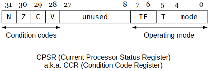
[31-28] Condition Codes
xxxxxxxxxx41N : Negative or less than flag2Z : Zero flag3C : Carry or borrow or extended flag4V : Overflow flag[27- 9] Reserved
[ 8- 0] System Control Bits
xxxxxxxxxx291IF : Enables or disables IRQ or FIQ interrupts2T : Thumb mode3Mode :4M[4:0] Mode ARM - Visible State Registers5------ -------------------------- --------------------------------------------6b10000 User r0-r14, PC, CPSR7(Normal user mode)8------ -------------------------- --------------------------------------------9b10001 FIQ r0-r7, r8_fiq-r14_fiq, PC CPSR, SPSR_fiq10(Fast Interrupt Request)11------ -------------------------- --------------------------------------------12b10010 IRQ r0-r12, r13_irq, r14_irq, PC CPSR, SPSR_irq13(Interrupt Request)14------ -------------------------- --------------------------------------------15b10011 Supervisor r0-r12, r13_svc, r14_svc, PC CPSR, SPSR_svc16(Software Interrupt17processing (SVC))18------ -------------------------- --------------------------------------------19b10111 Abort r0-r12, r13_abt, r14_abt, PC, CPSR, SPSR_abt20(Processing memory21faults)22------ -------------------------- --------------------------------------------23b11011 Undefined r0-r12, r13_und, r14_und, PC, CPSR, SPSR_und24(Undefined instruction25processing)26------ -------------------------- --------------------------------------------27b11111 System r0-r14, PC, CPSR28(Operating System)29------ -------------------------- --------------------------------------------[!] Note: So far, we have discussed only these 17 (including
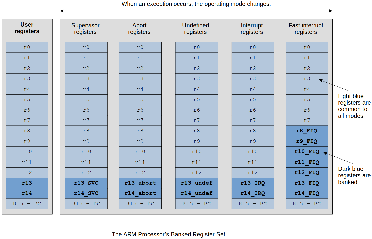
CPSR) registers that are visible to us in the user mode. In reality, however, ARM has total 32 registers (excludingCPSR) and the rest become visible as you switch to the different modes.(16 user mode registers) + (2 + 2 + 2 + 2 + 8 banked registers) = 32 registers
[!] Note: ARM designers decided to maintain another set of registers to make context switching more efficient by reducing the push/pop of all the registers to/from the stack.
Instead of having to push and pop all 16 registers every time there is an interrupt or mode change.
e.g., In SVC mode, it's got its own playground (
r13_SVC,r14_SVC) to handle its interrupt without messing other registers.This helps interrupts handled much faster since there's no need to push things onto the stack which is located in the main memory. (Access to main memory is orders of magnitude SLOWER.)
In the OS there are unique registers that are only available in that specific mode.
Specific ARM Exception Handling Sequence
The operating mode is changed to the mode corresponding to the exception.
e.g., An interrupt request would select
IRQmode.
The address of the instruction following the point at which the exception occurred is copied into register
r14 (lr).In other words, the exception is treated as a type of subroutine call and the return address is preserved in the link register.
The current value of the
CPSRis saved in theSPSRof the new mode.e.g., If the exception is an interrupt request,
CPSRgets saved inSPSR_irq.It is necessary to save the current processor status because an exception must not be allowed to modify the processor status.
Interrupt requests are disabled by setting bit
7of theCPSR.If the current exception is a fast interrupt request, further
FIQexceptions are disabled by setting bit 6 of theCPSR.
Each location in the exception table contains an instruction that is executed first in the exception handling routine.
This instruction is normally a branch operation (for example
B myHandler)This would load the program counter with the address of the corresponding current exception handler.
Following table defines the memory locations accessed by the ARM processor's exceptions.
Each memory location contains the first instruction of the appropriate exception handlers; this implies that this table should be in read-only memory.
xxxxxxxxxx91Exception Mode Vector Address2================================================ ========== ==============3Reset SVC 0x000000004Undefined instruction UND 0x000000045Software interrupt (SWI) SVC 0x000000086Prefetch abort (instruction fetch memory fault) Abort 0x0000000C7Data abort (data access memory fault) Abort 0x000000108IRQ (normal interrupt) IRQ 0x000000189FIQ (fast interrupt) FIQ 0x0000001C
Returning From an Exception
After the exception has been dealt with by a suitable handler, it is necessary to return to the point at which the exception was called (if the exception was fatal, a return is no longer possible.
In order to return from an exception, the information that defines the pre-exception mode must be restored;
PCPC, so it has got to be restoredCPSRThere are 2
CPSRs in ARM. When entering the ISR,CPSRgets copied into the auxiliaryCPSR, and when returning back to the user mode,CPSRgets overwritten by the contents of the auxiliaryCPSR.This takes two instructions to do! (see the following issue)
Returning from an exception is not as trivial a matter as it might seem. If you restore the
PCfirst, you are still in the exception-handling mode since theCPSRhasn't been restored back to the user mode yet. On the other hand, if you restore theCPSRfirst, you are no longer within the exception-handling routine and there is no way in which you can restore thePCand stuff.You can't use a normal sequence of operations to return from an exception because it involves a change of operating mode.
So, the ARM peope tweaked an existing instruction a little bit to create a special instruction that can restore bothPCandCPSRat the same time:2 exception return mechanisms are provided to solve this issue in one instruction.
Mechanism 1
r14.Mechanism 2
Moreover, the return mechanism depends on the type of exception being handled.
If you are returning from an exception where the return address is in the
link register, you can execute instructions described in the following table:xxxxxxxxxx131ARM Return from Exception Operations23Exception type Instruction to return to user mode4============================================ ==========================================5SWI, undefined instruction MOVS pc, r146- --7as long as the PC is listed first it8knows91) PC has to be restored AND102) CPSR mode has to be restored back11to user mode12IRQ, FIQ SUBS pc, r14, #413Data abort to repeat the faulted instruction SUBS pc, r14, #8MOVSandSUBSare special versions of the normal instructions used when the destination register is thePC. You have to modify the value of thePCwhen returning from anIRQ,FIQ, or adata abort.In the case of
IRQ, thePChas to be wound back byThis is because of the pipelining. By the time the interrupt was checked and the
PCwas saved onto the stack, thePChas already been updated once. (more to come later)
In the case of
FIQ, thePChas to be wound back byAgain because of the pipelining.
PCalready updated to the next next instruction was saved onto the stack.
If the exception handler has copied the return address onto the stack, you have to use a different mechanism.
Under normal circumstances, you would return from a subroutine with a stacked
PCby means of an instruction such asxxxxxxxxxx21LDMFD r13!, {r0-r4, PC} @ or POP {r0-r4, PC}2@ r0-r4 is the list of registers to be restored.If you wish to pop the saved registers and restore the
CPSRat the same time, you have to use the special version of this instruction:xxxxxxxxxx41LDMFD r13!, {r0-r4, PC}^ @ restore r0 through r42@ return and restore CPSR3@ or4POP {r0-r4, PC}^ @ this needs to be verified on the Raspberry PiThe
^symbol after the register list indicates that theCPSRis to be restored at the same time thePCis restored.The program counter was not modified at the point at which it was restored. You have to modify the
PCbefore you stack it!