Home | Projects | Notes > Computer Architecture & Organization > Sequential Circuits
Sequential Circuits
Combinational Circuits vs. Sequential Circuits

Combinational circuits
Outputs determined ONLY by its input(s).
Sequential circuits
Outputs determined by its input(s) and its previous state.
Basically a combinational circuit combined with a memory element. Memory element could be:
Latches - clock (X), therefore asynchronous
Flip-flops - clock (O), therefore synchronous
SR Latch (NOR)

An SR latch (Set/Reset) is an asynchronous device.
Relies only on the state of the S and R inputs.
Following is an SR latch created with two NOR gates that have a cross-feedback loop.
Can also be made from NAND gates, but the inputs are swapped and negated.
Clocked SR Flip-Flop (AND-NOR)
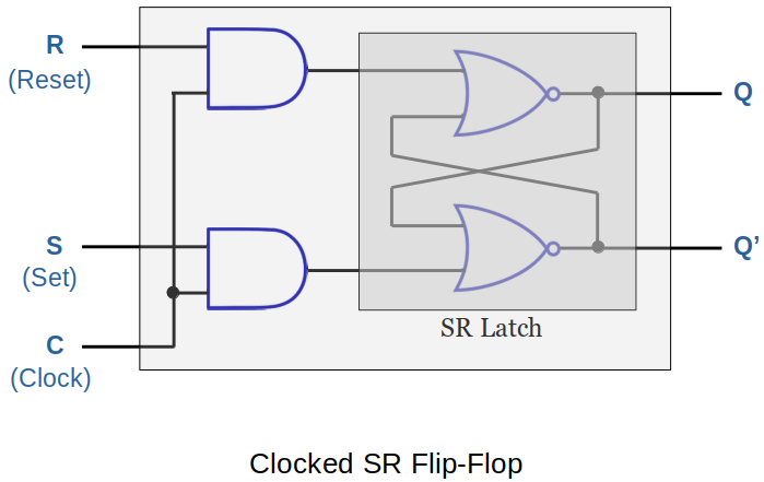
An SR flip-flop is a synchronous device.
Following SR filp-flop is built from a pair of AND gates added to a basic SR latch made from NOR gates.
Analysis
When (clock) signal stays
0, the flip-flop maintains the previous state. (∵ Two AND gates are disabled.)When C stays
1, the filp-flop behaves like the standard SR latch.
D (Data) Flip-Flop
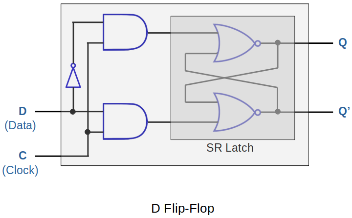
Why can't we just tell it what we want to store and not worry about S and R values? (So, we have D flop-flop!)
Analysis
The D flip-flop captures the value of the D-input at a definite portion of the clock cycle (such as the rising edge of the clock). That captured value becomes the Q-output.
At other times, the output-Q maintains the previous value.
Registers
A register is a group of flip-flops which share a common clock.
An
May have additional logic to allow for other functions.
4-Bit Register with Parallel Load
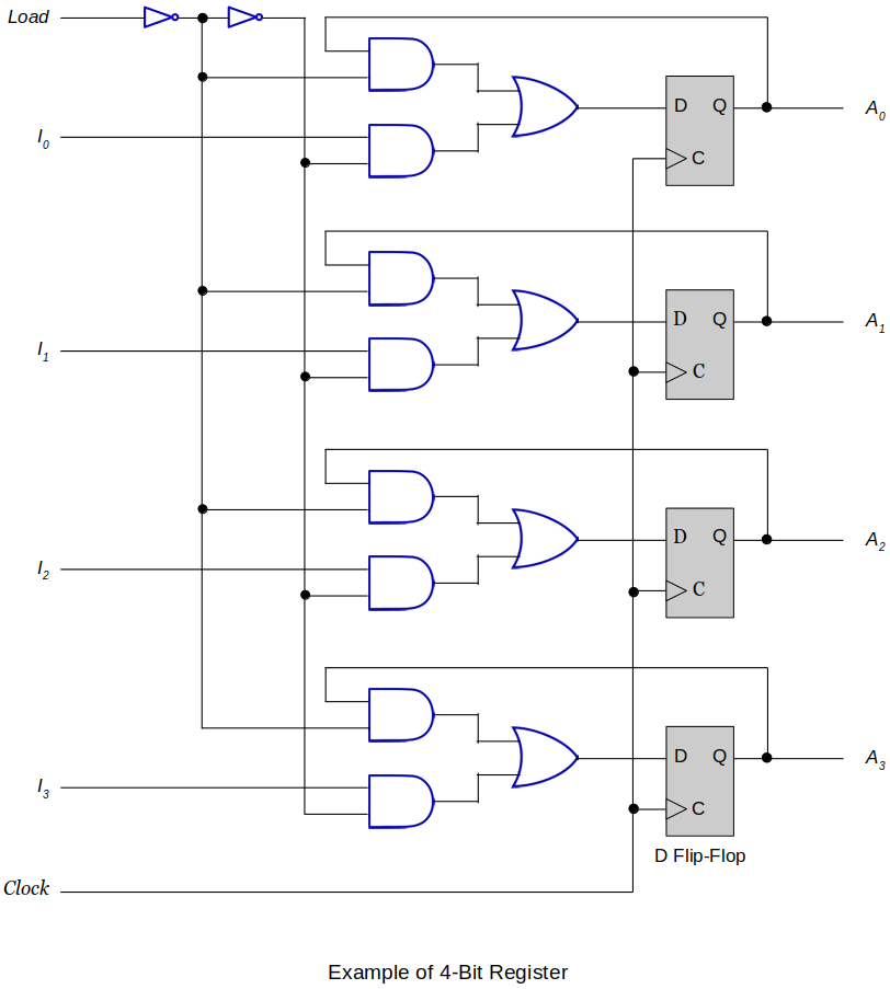
When
Load = 1The lower of the each AND gate pair will be enabled, and the upper AND gates will be disabled.
The values
I0 ~ I3will then be stored into the flip-flops at a definite portion of the clock cycle (such as the rising edge of the clock.)
When
Load = 0The upper of the each AND gate pair will be enabled, and the lower AND gates will be disabled.
The values stored in each D filp-flop will remain unchanged due to the feedback loop.
4-Bit Register with Parallel Load (Improved Design with Fewer Gates)
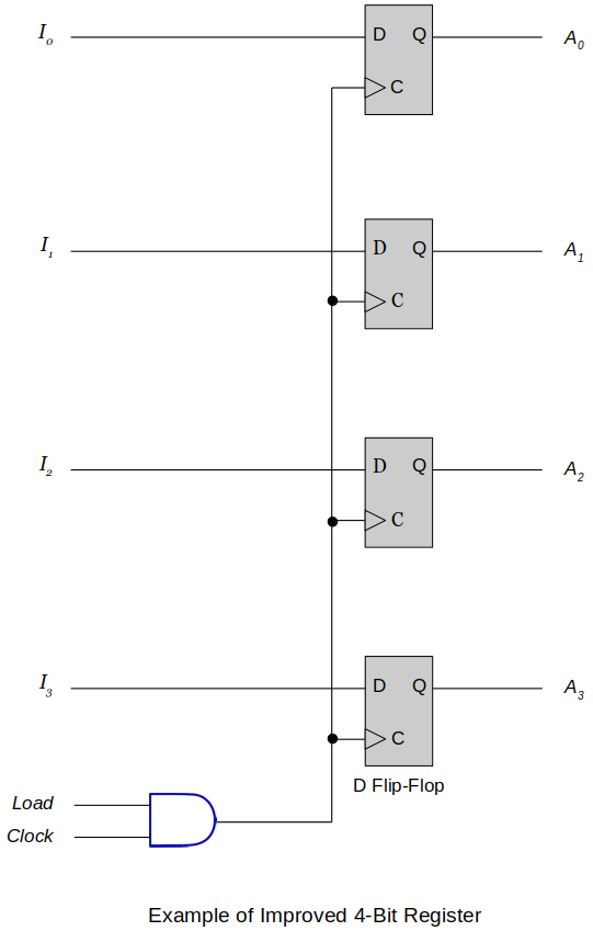
How you can keep the D flip-flops from changing the values when you don't want them to change with fewer gates?
Introduce an AND gate into the clock path!
Shift Registers

A shift register moves the bits stored in it one or more positions to the right or left.
Moving to the right divides the binary number by 2.
Moving to the left multiplies the binary number by 2.
In the following example, four clock cycle will be required to completely load a 4-bit data.
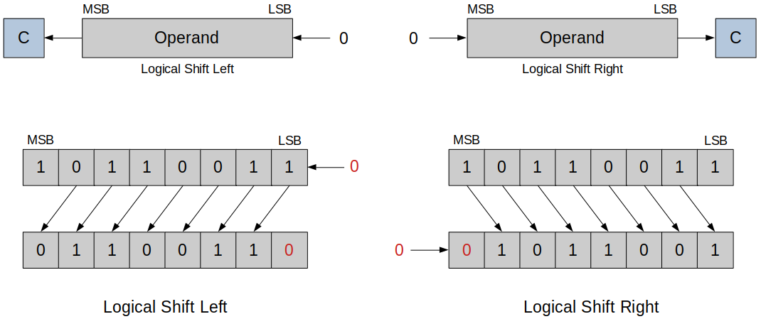
Logical shift
Logical Shift Left
Each bit is shifted towards left, MSB is discarded and LSB becomes 0.
Logical Shift Right
Each bit is shifted towards right, LSB is discarded and MSB becomes 0.
Arithmetic shift
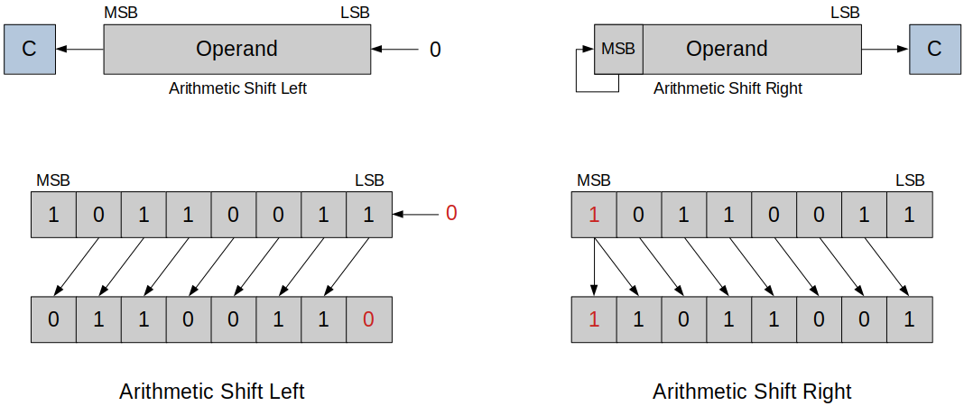
Arithmetic Shift Left
Each bit is shifted towards left, MSB is discarded and LSB becomes 0. (Similar to logical shift)
In this example, the operation has overflowed. Meaning, the result of the multiplication is larger than the largest possible value.
Arithmetic Shift Right
Each bit is shifted towards right, LSB is discarded and MSB is preserved.
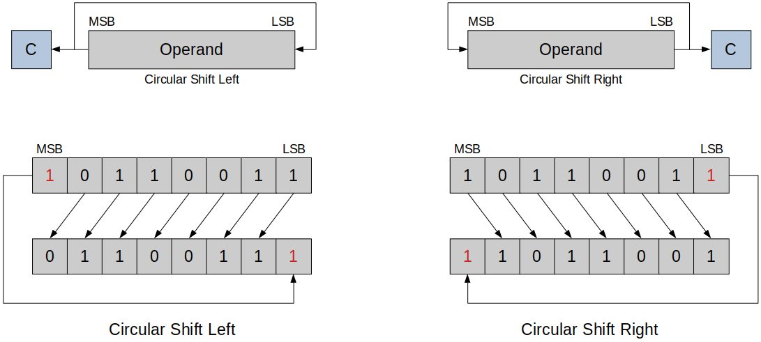
Circular shift
The bit that would be lost is moved into the register.
Applications of Shift Registers
Serial Transfer from One Register to Another
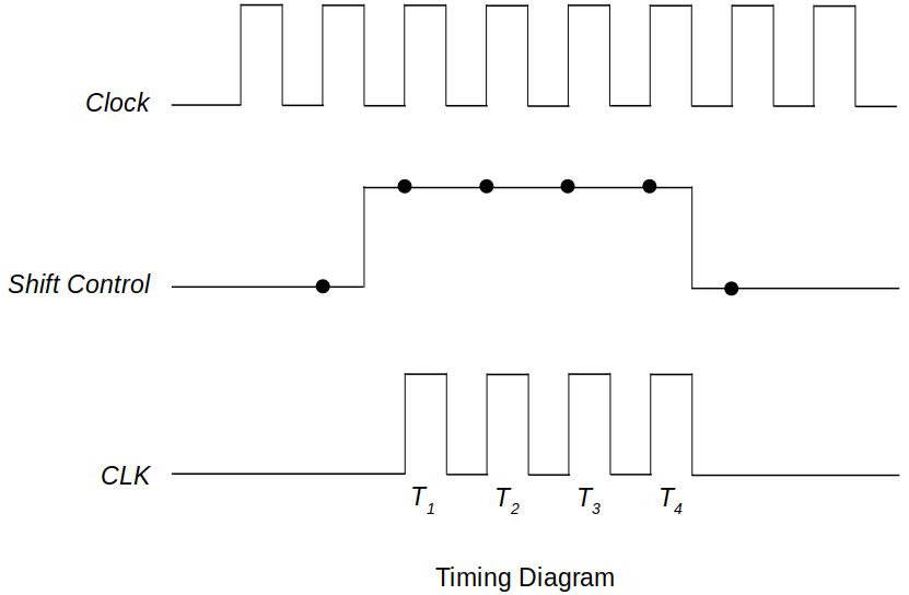
Following example demonstrates a serial transfer of a 4-bit data from one register to another.
It will take exactly four clock cycles for the contents stored in A to be completely transferred to B.
When shift control is high, at each clock pulse, one bit at a time is copied from A to B.
The feedback formed by SOA and SIA helps A retain its value after the completion of the data transfer.
This circuit is easy to build and cheap, but not fast.

Serial Adder
Following example demonstrates
A = A + Boperation where the sum ofAandBgets stored intoA. (A's original value is overwritten.)D flip-flop holds the carry of the previous sum and when an appropriate clock cycle hits this carry will be transferred into the full adder to be added with new
xandy.
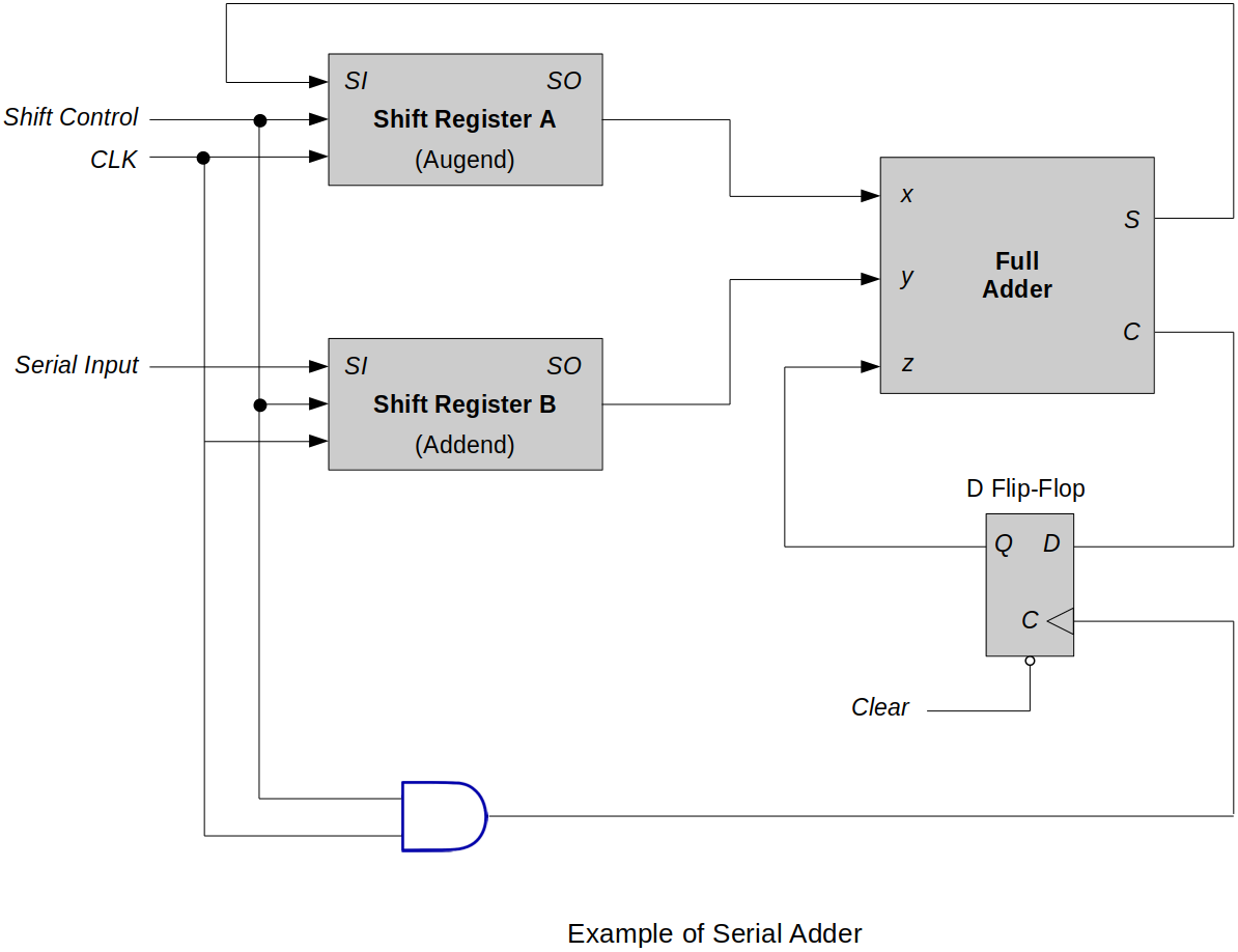
One problem with this circuit is that
Bwon't retain its value after the operation, which is far from how modern computer systems handle this.Some improvements can be made to make this circuit more functional.
Make Shift Register B a circular shift register so that it retains its original value after the operation.
Add another register so that the circuit performs
C = A + B.