Home | Projects | Notes > Computer Architecture & Organization > State Machine & Flow Chart
State Machine & Flow Chart
State Machine
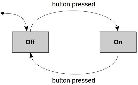
A state machine is a behavior model. It consists of a finite number of states and is therefore also called finite-state machine (FSM).
Based on the current state and a given input the machine performs state transitions and produces outputs.
At any instant, a system may be in one of several possible states.
In a digital world, a change from one state to another occurs when an event (such as a clock pulse) takes place.
Example:

Flow Chart
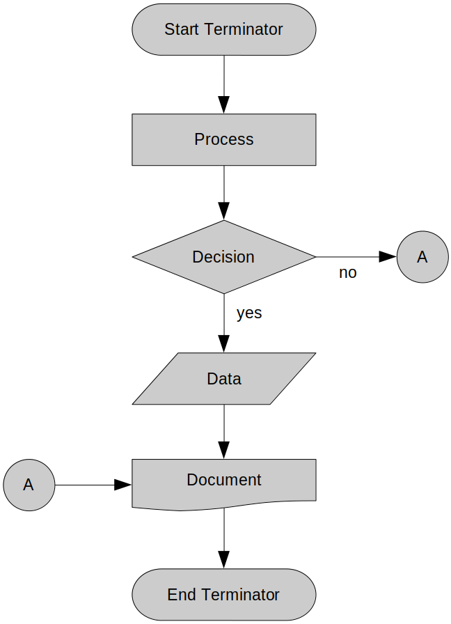
A flow chart is a type of diagram that represents a work-flow or process.

Different flow chart symbols have different meanings. The most common flow char symbols are:
Terminator: An oval flow chart shape indicating the start or end of the process.
Process: A rectangular flow chart shape indicating a normal process flow step.
Decision: A diamond flow chart shape indication a branch in the process flow.
Connector: A small, labeled, circular flow chart shape used to indicate a jump in the process flow. (Shown as the circle with the letter "A", in the diagram aobve.)
Data: A parallelogram that indicates data input or output (I/O) for a process.
Document: Used to indicate a document or report.