Home | Projects | Notes > Computer Architecture & Organization > Cache Memory
Cache Memory
Passing Arguments to a Function
In higher level languages, there are a couple of concepts in regards to passing arguments to a function, returning values from a function. (e.g., Pass by value, pass by reference) However, at assembly language level (low level), there's no such concepts. The programmer has to keep track of the parameters that are passed between the routines.
Passing of arguments can be done several different ways in assembly:
Just have global variables defined in the data section and the subroutine has direct access to them.
The data is put in specific registers in the calling routine and the subroutine knows which registers contain what it needs to work on.
e.g., With the
printfr0contains the address of the string andr1r2,r3contain any data that may be printed with proper format specifiers such as%d,%c, etc.
The data is pushed onto the stack by the calling routine and the subroutine knows what order they are pushed so they can pop and do the operations.
Returning data can be done in the same way:
Using global variables
Using registers
Using stack
Pick a method and stick with it.
Or adopt the C convention with using registers
r0-r3to pass to the function and return values viar0.In C, only the first 4 arguments are passed via registers, and anything beyond that are passed via the stack. Passing arguments via registers is the fastest way. Using stack is much slower process since it involves memory access.
xxxxxxxxxx31func(w, x, y, z, a, b, c)2---------- -------3via registers via stackTo make the code run faster, make sure to define all functions to have 4 or less parameters.
One solution is passing structures instead of individual variables but passing structures still fall under the 4-parameter-rule.
Subroutine Call and Return
Non-ARM, CISC Example: Typically, stack is used to keep track of the important information associated with the subroutine call and return. (Push the return address (PC) onto the stack before entering the subroutine, pop the return address from the stack and store it back to PC to return to where it was.
xxxxxxxxxx101Situation: The instruction BSR Proc_A calls subroutine Proc_A.23The processor saves the address of the next instruction to be executed in a safe place,4and loads the program counter with the address of the first instruction in the5subroutine.67At the end of the subroutine, a return from subroutine instruction (RTS) causes the8processor to return to the point immediately following the subroutine call.910CISC processors typically use a stack to support calls to and returns from subroutines.Code:
xxxxxxxxxx91BSR Proc_A @ saves the address of the next instruction to be executed (PC) in the2@ stack (this is what 'bl' in ARM assembly does)3...45Proc_A67...89RTS @ end of the subroutine; return (restores the PC from the stack)^RISC proessors do not go that far with their support. In some cases, they offer none.
In ARM, there is the
BLinstruction which is used for the call to the subroutine. However, there is no return from subroutine instruction for the ARM. Therefore, callingBLagain inside the subroutine will overwrite the link register (LR) which holds the previous return address. Problem!!!
ARM Support for Subroutines
ARM processors do not provide a fully automatic subroutine call/return mechanism like CISC processors do.
ARM's branch with link instruction,
BL, automatically saves the return address in registerr14which is also called the link register.The branch with link instruction behaves like the corresponding branch instruction but also copies the return address (i.e., address of the next instruction to be executed following a return) into the link register
r14.xxxxxxxxxx31BL Sub_A @ Branch to "Sub_A" with link2@ Save return address in r143@ RTL: [r14] ← [PC]Here, the ARM executes a branch to the target address specified by the label Sub_A. It also copies the program counter held in register
r15into the link registerr14to preserve the return address.At the end of the subroutine, it returns by transferring the return address in
r14to the program counter:xxxxxxxxxx11MOV pc, lr @ MOV r15, r14To evaluate
if x > 0 then x = 16x+1, else x = 32xseveral times in a program (assuming that.xis inr0; meaning passing the value ofxviar0):xxxxxxxxxx171Func1:2CMP r0, #0 @ Test for x > 03MOVGT r0, r0, LSL #4 @ If x > 0 then x = 16x4ADDGT r0, r0, #1 @ If x > 0 then x = 16x + 15MOVLT r0, r0, LSL $5 @ Else if x < 0 then x = 32x6MOV pc, lr @ Return by restoring saved PC78@ Application of the subroutine9LDR r0, [r4] @ Get P10BL Func1 @ P = (if P > 0 then 16P + 1 else 32P) ; first call11@ BL automatically does [lr] ← [PC] here12STR r0, [r4] @ Save P1314LDR r0, [r5, #20] @ Get Q15BL Func1 @ Q = (if Q > 0 then 16Q + 1 else 32Q) ; second call16@ BL automatically does [lr] ← [PC] here17STR r0, [r5, #20] @ Save PImagine how the code would have looked like if ARM did not support the subroutine call.
If there is another BL call in a subroutine, then the linked register
r14will be overwritten. Will show the fix later.
Conditional Subroutine Calls
The branch with link can be conditionally executed:
xxxxxxxxxx21CMP r9, r42BLLT ABC @ Branch to ABC if [r9] < [r4]If there is another BL call in a subroutine, then the linked register
r14will be overwritten. Will show the fix later.
Subroutines and the Stack
The stack is a last in first out (LIFO) data structure.
The queue is a first in first out (FIFO) data structure.
Inside a CPU is the stack and the queue that are implemented with shift registers. However, these are limited in size.
Stacks in microprocessors are implemented by using a stack pointer to point to the top of the stack in main memory.
Possible stack structures:
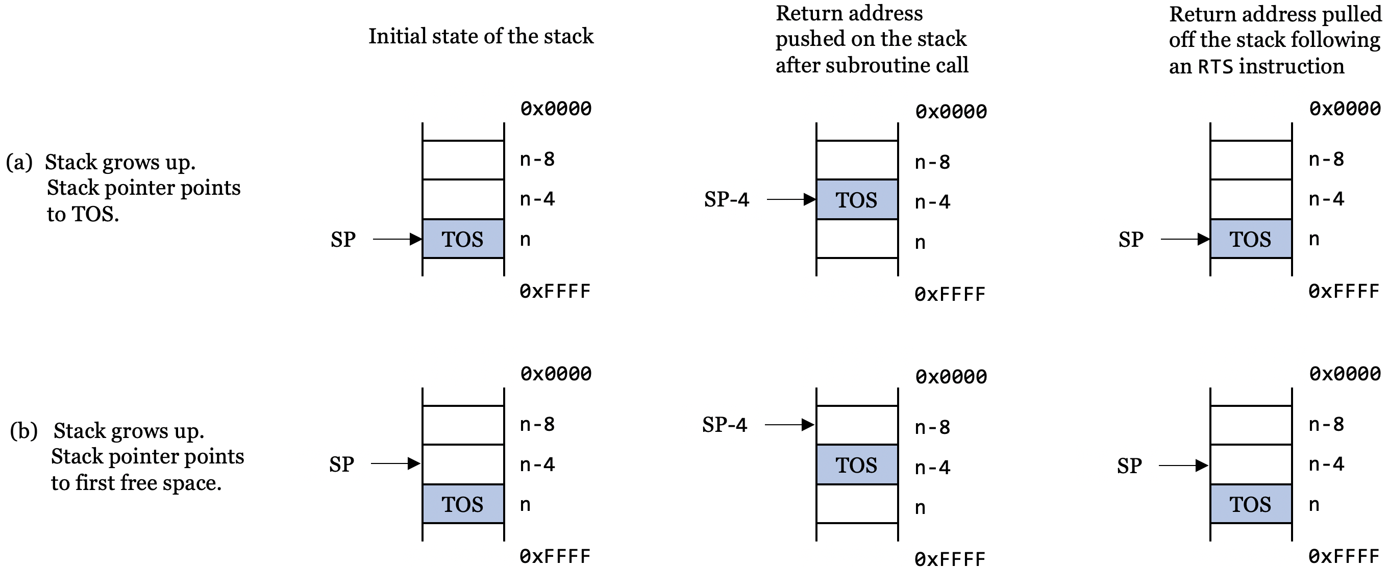
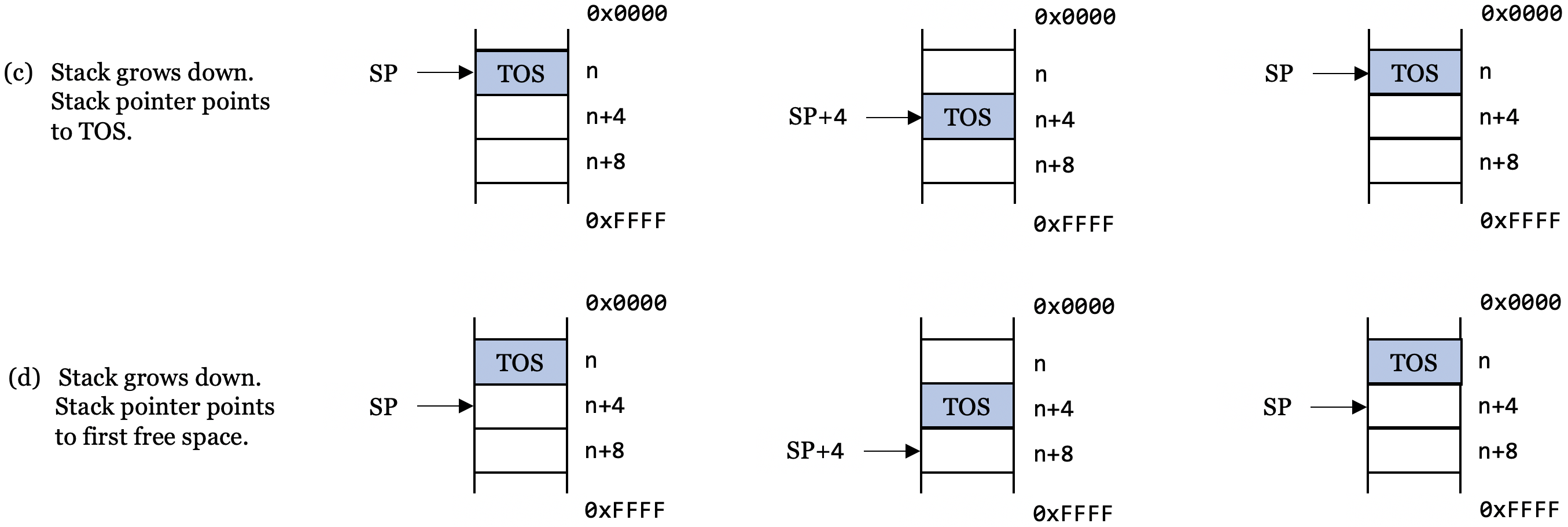
TOSstands for "top of stack" (the element at the top of the stack). By convention, up refers to the top of the page and lower address. This can be confusing.These diagrams assume byte-addressed memory and that each element on the stack is 32 bits (4 bytes).
Just know that the stak can be implemented in different ways. When programming, don't worry about it and just use
PUSH/POP.An important application of the stack is to save return addresses after a subroutine call.
CISC processors maintain the stack automatically.
RISC processors force the programmer to maintain the stack.
If there are nested subroutine calls, it is the programmer's responsibility to make sure that each subroutine's return address (the value stored in the linked register
r14) is pushed onto the stack. Otherwise, a subroutine's return address will be overwritten by the subsequent subroutine's return address.
Leaf Routines
A leaf routine does not call another routine. It is at the end of the tree. If you call a leaf routine with
BL, the return address is saved in the linked registerr14. A return to the calling point is made with:xxxxxxxxxx11MOV pc, lr @ Not necessary to use stack since there is no more sutroutine.If the routine is not a leaf routine, you cannot call another routine without first saving the link register.
xxxxxxxxxx171BL XYZ @ Call a simple leaf routine2...3BL XYZ1 @ Call a routine that calls a nested routine4...56XYZ:7@ Code (This is the leaf routine)8...9MOV pc, lr @ Copy link register into PC and return1011XYZ1:12PUSH {r0-r4, lr} @ Save working registers and link register13@ r0-r4 may be parameters of a routine14...15BL XYZ @ Call XYZ; Overwrites the old link register16...17POP {r0-r4, pc} @ Restore registers and force a returnSubroutine
XYZis a leaf subroutine that does not call a nested subroutine and, therefore, we don't have to worry about the link register, and we can return by executingMOV pc, lr.Subroutine
XYZ1contains a call to a nested subroutine and we have to save the link register in order to return fromXYZ1.The simplest way of saving the link register is to push it on the stack. In this case we use a 'store multiple registers' instruction and also save registers
r0tor4.When returning from
XYZ1, we restore the registers and load the savedr14(the return address in the link register) into the program counter.
Laod and Store Multiple Registers to / from Stack
When subroutines use the same registers you are using there will be a problem. The ARM has two instructions which makes saving and restoring registers very quick and easy.
xxxxxxxxxx71LDMcdum reg!, mreg @ cd: condition code, um: update mode2STMcdum reg!, mreg34@ IA increment starting from reg5@ IB increment starting from reg + 46@ DA decrement starting from reg7@ DB decrement starting from reg - 4The important thing is to be consistent in how you use it and DO NOT mix them up.
xxxxxxxxxx41@ Following can be used to copy data stored in multiple locations in memory to somewhere2else.3STMDB sp!, {r0-r5} @ Stack pointer (sp) contains the starting address4LDMIA sp!, {r0-r5}The GNU assembler does allow for pseudo-instructions for
pushandpopso you do not have to remember which update mode to use.xxxxxxxxxx31PUSH {r1, r2, r3}2POP {r1, r2, r3}3@ Both allow for cd (conditional execution)On the Raspberry Pi this is the simplest thing to use. More examples:
xxxxxxxxxx31PUSH {r0, r4-r7}2PUSH {r2, lr}3POP {r0, r10, pc}In programs, the
PUSHandPOPshould always match.xxxxxxxxxx31PUSH {r0-r3, r10}2...3POP {r0-r3, r10}