Home | Projects | Notes > Embedded Systems Design using UML State Machines > Finite State Machine (FSM)
Finite State Machine (FSM)
Finite State Machine
A state machine is a software model of computation that comprises a finite number of states. Hence, it is also called a Finite State Machine (FSM).
Since states are finite, there is a finite number of transitions among the states. Transitions are triggered by the input events fed to the state machine (FSM is an event-driven system).
A state machine also produces output. The output produced depends on the current state of the state machine and the input events fed to it.
Benefits of Using State Machines (FSMs)
Used to describe situations or scenarios within your application (modeling the life cycle of a reactive object through interconnections of states).
Here, object means an instance of a class.
FSMs are helpful for modeling complex applications that involve extensive decision-making, generating various outputs (actions), and processing numerous events.
State machines are visualized using state machine diagrams in the form of state charts, which facilitate communication between non-developers and developers.
FSMs can be a means to help effective communication between cross-functional teams.
They make it easier to visualize and implement changes to the project's behavior.
A complex application can be depicted as a collection of different states processing a fixed set of events and generating a fixed set of outputs.
Loose coupling: An application can be divided into multiple behaviors or state machines, with each unit testable separately and potentially reusable in other applications.
Simplifies debugging and enhances code maintenance.
Offers scalability.
Simplifies the overall application complexity by breaking it down into state-level complexity for analysis and implementation.
Types of State Machines
Mealy machines
Moore machines
Harel state charts
UML state machines
Mealy Machine
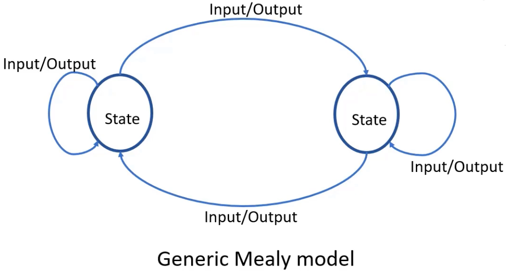
In this machine, the output produced by the state machine depends on the input events fed to the state machine AND the current active state of the state machine.
The output is NOT produced within the state. Instead, the output is produced along the transition from one state to another.
State transition: Changing the state from one to another
Output is represented alongside each input, separated by a '/'.
An "Output" is also referred to as an "Action."
In the Mealy model, the "Output" is also called as an "Input action."
Example: Light control system
Mealy state machine
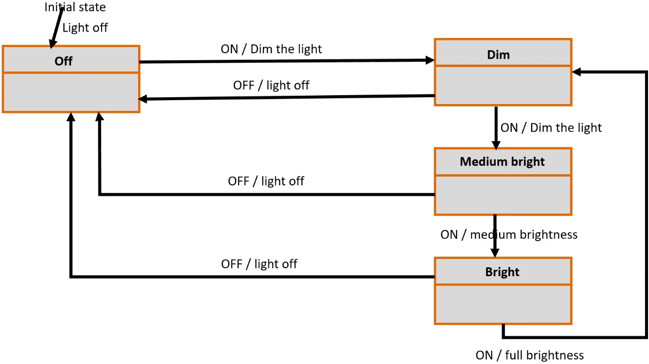
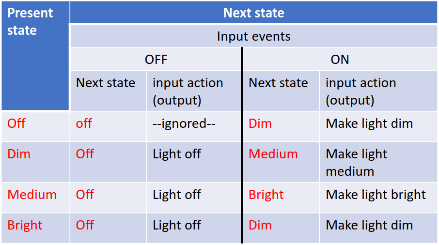
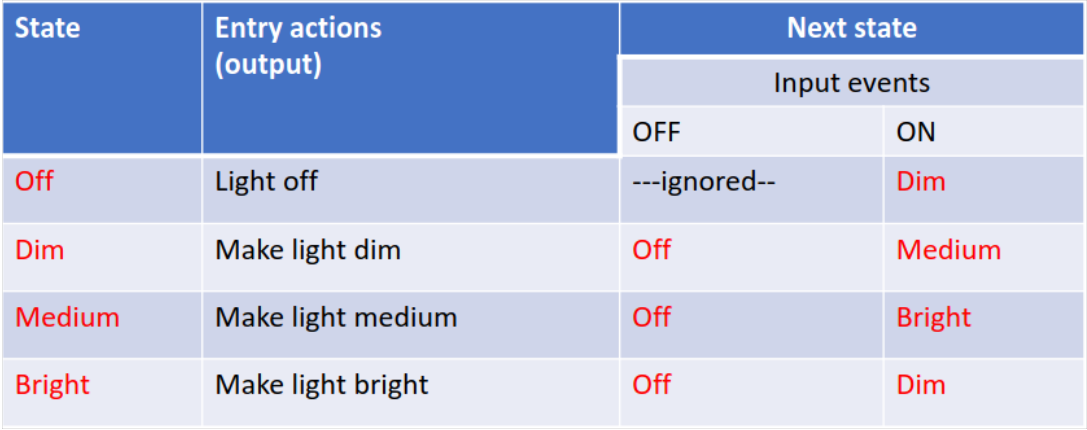
State transition table
State transition table helps implement the code.
When the state machine is in the "Off" state, and if
the input event "ON" is received, the state machine produces the output "Make light dim" and transitions to the "Dim" state.
the input event "OFF" is received, it is ignored.
Moore Machine
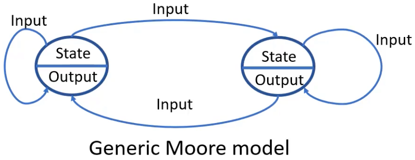
In this machine, the output is determined solely by the current active state of the state machine and is not influenced by any input events.
There is NO output during state transitions.
Output is represented within the state.
"Output" is also commonly referred to as an "Action."
In the Moore model, the "Output" is also known as an "Entry action."
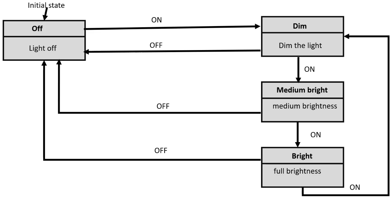
Example: Light control system
Moore state machine
In this case, all the "Actions (or Entry Actions or Outputs)" are assigned to each state.
State transition table
Harel State Chart
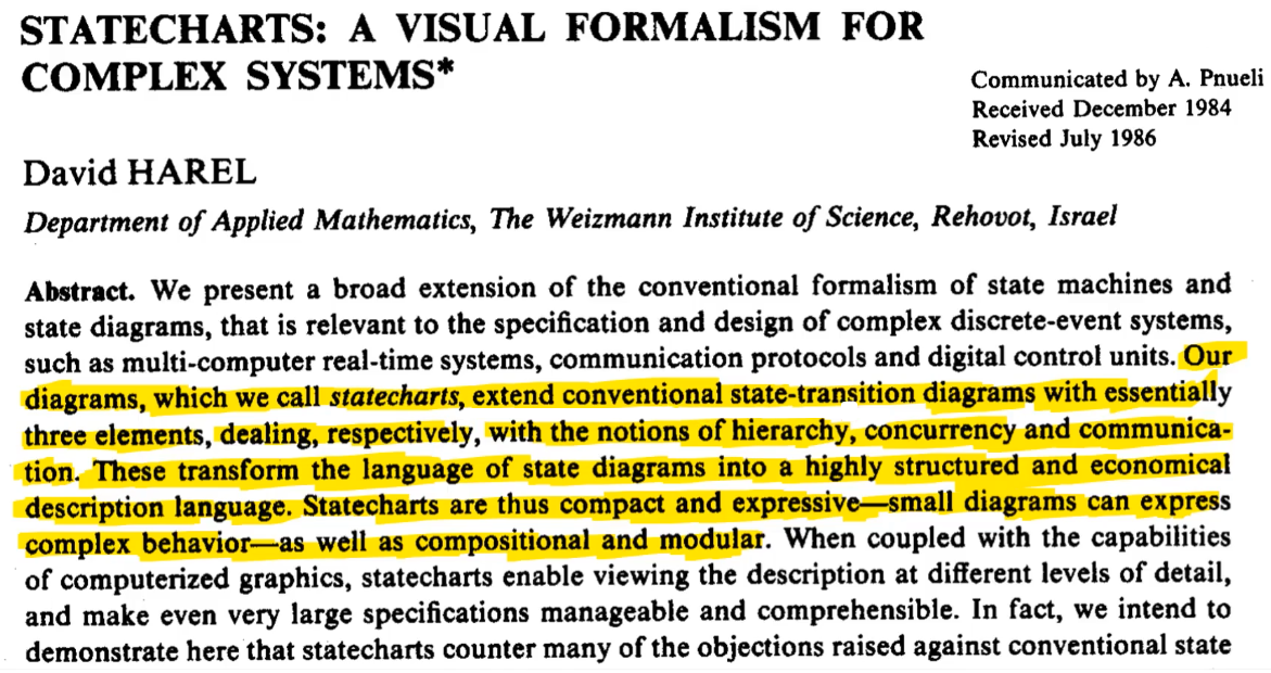
Harel state charts features
Substates and superstates
Composite states
History states(shallow and deep)
Orthogonality
Communication between state machines
Conditional transitions (guards)
Entry and exit actions
Activities inside a state
Parameterized states
Overlapping states
Recursive statecharts
UML State Machines
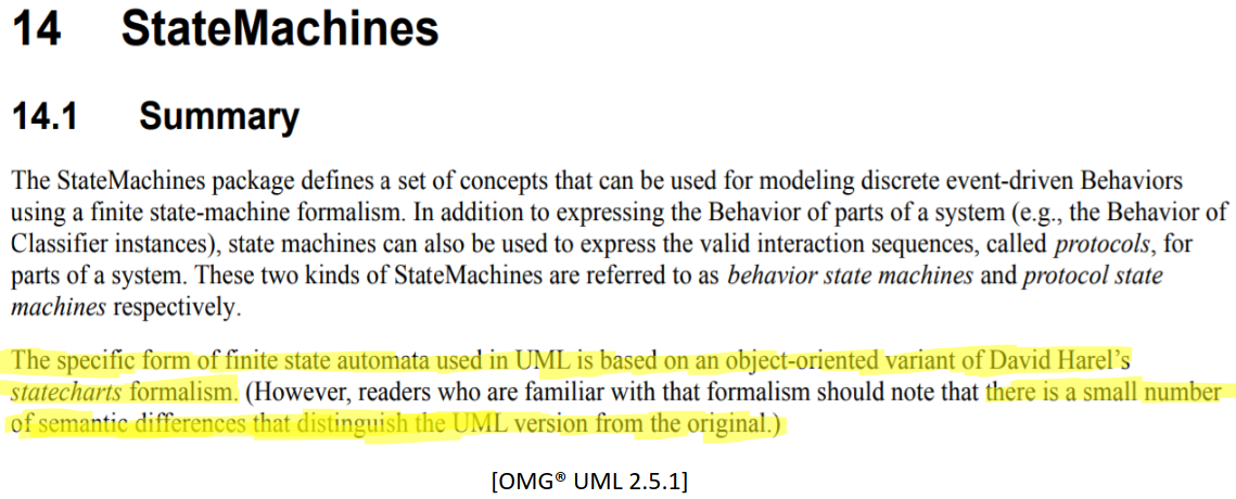
UML Modeling Tool & Code Generator
Rhapsody by IBM
QM Model-based design tool by Quantum Leaps, LLC
Visual State by IAR
Yakindu state chart tools by Itemis AG
Implementation of State Machine Handler
Nested switch-case approach
State table approach
State handler approach
Most efficient, less redundant
Originally described in the book "Practical UML Statecharts in C/C++: Event-Driven Programming for Embedded Systems [SECOND EDITION] by Miro Samek"