Home | Projects | Notes > Embedded Systems Design using UML State Machines > State
State
What is a State?
A state represents a distinct stage of an object's life cycle.
Here, an object refers to an instance of a class or a structure.
An object, in its life cycle, can pass through a number of stages in an application.
A state model is a situation in the execution of a State Machine behavior during which some invariant condition holds. In most cases, this condition is not explicitly defined but is implied, usually through the name associated with the State. (OMG UML 2.5.1)
How to Identify States?
Map different scenarios through which an object life cycle passes into number of states.
Example: Different scenarios of Protimer Application (see Exercise 2: Productivity Timer (ProTimer))
The followings are the states that an object goes through during its life cycle in the Protimer application:
IDLE
TIME-SET
COUNTDOWN
PAUSE
STAT
An application may contain several objects, and for each object there could be a corresponding state machine model.
How to Create a State?
Draw a round-conrnered rectangle
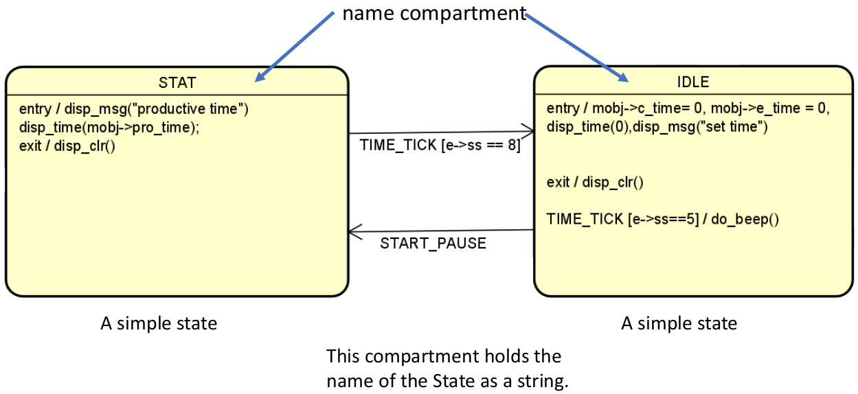
Create a horizontal name compartment
Give a name that is unique within the state machine diagram
Types of States in UML
Simple State
A state that doesn't have any substates, transitions, regions, submachines
NO two states in the state machine diagram can be the same. (Each name must be UNIQUE within the diagram.)
The following diagram shows a simple state with name compartments.
Composite State
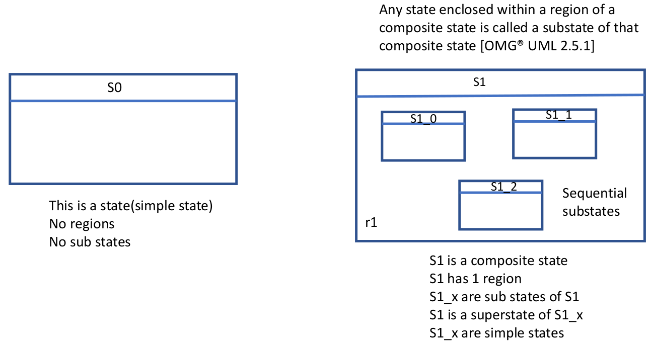
A state which has substates, and contains at least one region
Helps making your state machine diagram much simpler by reducing the clutter in the diagram
Types of composite state:
Simple composite state - Has exactly one region
Orthogonal state
By using composite states, you can express state hierarchies.
It makes statecharts more comprehensible by reducing the number of transistions between states.
Simple states vs composite states:
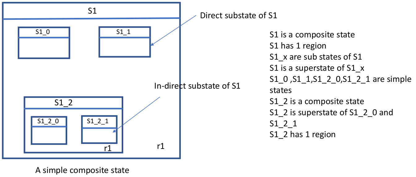
Substates form a region (e.g., S1 has one region identified as r1)
Understand the term "direct substate" and "indirect substate" in the following example.
Submachine State
A submachine state specifies the insertion of the specification of a submachine state machine.
The state machine that contains the submachine state is called the containing state machine.
Pseudo States
Initial - Starting point for a region
Choice - Diamond-shaped symbol with a single incoming transition and two or more outgoing transitions
Join
Deep history
Shallow history
See [OMG
Compartments of a State
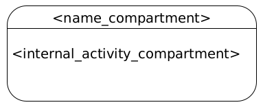
A simple state contains two compartments:
Name compartment
Internal activities compartment
Name Compartment
Where the name of a state goes.
Internal Activity Compartment
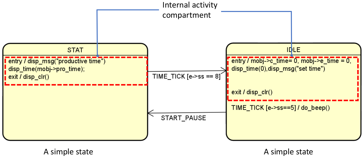
The internal activities compartment defines a list of internal behaviors associated with a state.
Each entry has the following format:
xxxxxxxxxx11<behavior-type-label>[/<bahavior-expression>]Example:
entry,exit,doare internal activities labels or keywords defined in the UML. Do not use these keywords outside the internal activity compartment to represent events in the state machine diagram. These labels identify the circumstances under which the behaviors specified by the<behavior-expression>is executed.entryBehavior identified by
<behavior-expression>will be executed upon entry to the state. Use theentrykeyword if the state has entry action. (When entering into a composite state, the entry actions are executed beginning from the outermost state to the innermost state)exitBehavior identified by
<behavior-expression>will be executed upon exit from the state. Use theexitkeyword if a state has exit action. (When exiting from a composite state, the exit actions are executed beginning from the innermost state to the outermost state.)doBehavior identified by
<behavior-expression>will be executed as long as the object is in the state or until the computation specified by the expression is completed. This represents ongoing behavior. Use thedokeyword only if a state hasdoaction.
Whether your state requires these internal activities or not depends on your project requirements and how you design your state machine. All these are optional. A state may or may not have the
entryorexitactions.
Notes
The
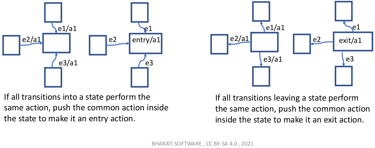
doactivity behavior commences only after the state'sentrybehavior has completed.entry,exit,do, cannot be associated with any transitions.If all transitions into / out from a state perform the same action, consider specifying the action inside the state to make the diagram less cluttered.
