Home | Projects | Notes > MCU Peripheral Drivers > Introduction to GPIO
Introduction to GPIO
General Purpose Input/Output (GPIO)
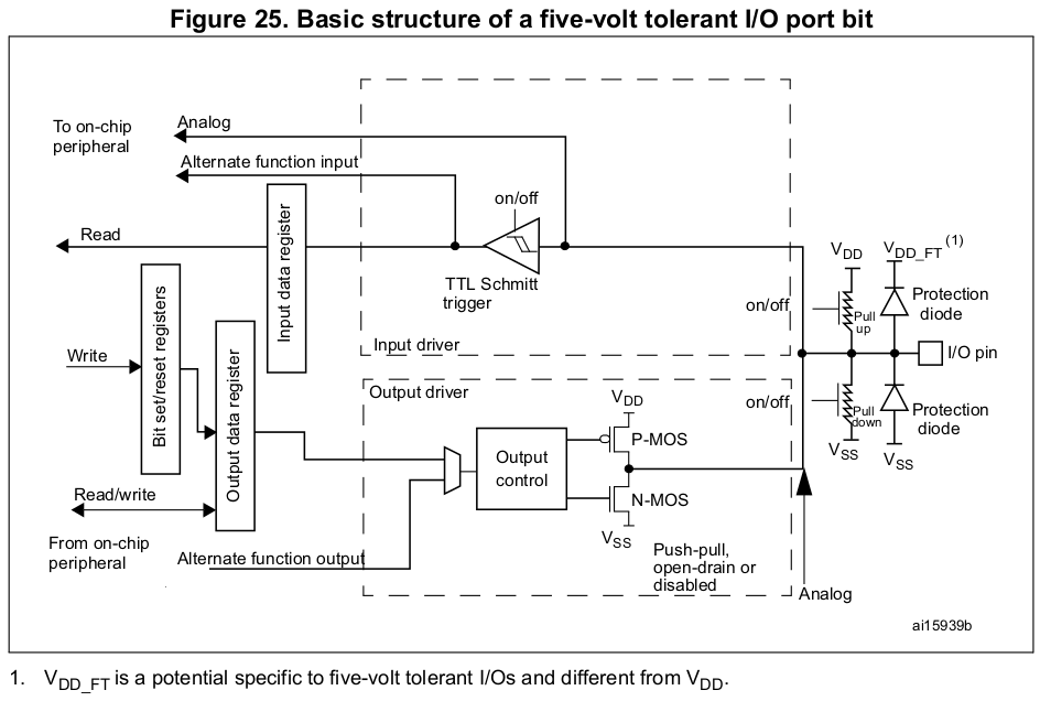
A GPIO pin can be used for many purposes as shown below. This is why it is called as "General purpose". (Some pins of an MCU cannot be usd for all these purposes. So, those are called as "Pins" but not as "GPIOs".)
A GPIO pin of MCU can be operate in:
Input mode
Interrupt - When an MCU pin is in input mode, it can be configured to issue an interrupt to the processor.
Output mode
Alternate function mode
Analog mode
Input Mode
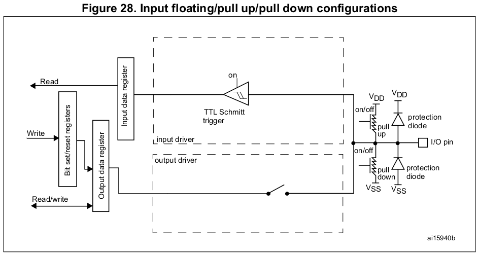
When an I/O pin is programmed as input mode:
The output buffer is disabled.
The Schmitt trigger input is activated.
The pull-up and pull-down resistors are activated depending on the value in the
GPIOx_PUPDRregister.The data present on the I/O pin are sampled into the input data register every AHB1 clock cycle.
A read access to the input data register provides the I/O state.
High impedance (HI-Z) state (a.k.a. Floating state)
HI-Z state of an I/O pin is keeping the pin floating by NOT connecting it to the high or low voltage level.
After you power up the MCU, by default, all the GPIO pins will be in input mode with HIGH-Z state or floating state. (This is true with most of the MCUs.)
Keeping a pin in a floating state can cause leakage current which may lead to higher power consumption. This is because a floating pin is highly susceptible to the circuit voltage noise and may result in leakage current.
Pull-up/pull-down state
Floating state of a pin can be avoided by introducing an internal pull-up or pull-down resistor.

There are configuration registers for every GPIO port which enable you to handle internal pull-up or pull-down resistors.
It is always safe to keep the unused GPIO pin in one of the states so that they are reluctant to voltage fluctuations which may lead to leakage of current.
Output Mode
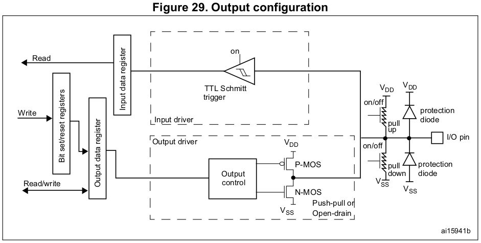
When an I/O pin is programmed as output mode:
The input buffer is still on. Therefore you can read the state of an I/O pin through the Input Data Register. (Reading is possible.)
Open-drain configuration
Basically the default configuration (i.e., push-pull) of an output mode pin without the top PMOS transistor. (Only the NMOS transistor is present.)
When the transistor is switched ON, the output will be pulled down to LOW (i.e., GND).
When the transistor is switched OFF, the drain will be open, and the output will be in floating state.
An open-drain output configuration can only pull-down the pin, but it cannot pull-up the pin. It provides only 2 states; GND and float.
The open drain output configuration of a GPIO is useless until you provide the pull-up capacity (e.g., internal/external pull-up resistor).
Open-drain with pull-up resistor
Open-drain with internal pull-up resistor
Case of the most of the modern MCUs
Activated/deactivated via GPIO control registers
Open-drain with external pull-up resistor
If your MCU does not support internal pull-up resistor, which is very unlikely for modern MCUs, you may have to add an external pull-up resistor by yourself.
How to drive an LED from an output mode open-drain configuration GPIO pin?
Using internal pull-up resistor:
Activate the internal pull-up resistor
Connect the pin to the LED
Write 1 to input
Write 0 to input
Remember! Always activate and use the internal pull-up resistor of an I/O pin instead of connecting external resistors by hand unless you have a valid design issues with the internal one.
Push-pull configuration
Default configuration of an output mode pin.
In the push-pull configuration you don't need any pull-up or pull-down resistor.
When the top transistor (PMOS) is ON, the output will be HIGH.
When the bottom transistor (NMOS) is ON, the output will be LOW.
How to drive an LED from an output mode push-pull configuration GPIO pin?
It is not necessary to use the pull-up resistor in order to drive an LED using push-pull configuration.
Write 1 to input
Write 0 to input
Alternate Function Mode
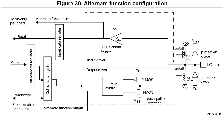
When an I/O pin is programmed as alternate function mode:
The pin will be assigned for alternate functionalities. (For STM32F407 MCU, there are 16 possible alternate functionalities,
AF0-AF15, that can be configured to the GPIO pins. Not every pin support all 16 functionalities and this information can be found in the data sheet of the MCU; "Alternate function mapping")Example - List out all the 16 possible alternate functionalities supported by GPIO port A pin number 8 (i.e., GPIOA.8)
MODE (AFx) Functionality AF0 MCO1 AF1 TIM1_CH1 AF2 (Not supported) AF3 (Not supported) AF4 I2C3_SCL AF5 (Not supported) AF6 (Not supported) AF7 USART1_CK AF8 (Not supported) AF9 (Not supported) AF10 OTG_FS_SOF AF11 (Not supported) AF12 (Not supported) AF13 (Not supported) AF14 (Not supported) AF15 EVENTOUT
Circuit analysis
Output part
The Output Data Register has no control over the Output Control Block. The Output Control Block is now controlled by the Alternate Function Output.
The pin is controlled by assigned peripheral output functionality like
I2C_SDA,I2C_CLK,UART_TX, etc.Input part
The pin is ready by assigned peripheral input functionality like
USART_RX,ADCIN,TIMER_CHx,CAN_RX, etc.
Summary
By taking various modes and pull-up/pull-down resistors combinations, the following configurations can be obtained for a GPIO pin:
Input floating
Input pull-up
Input-pull-down
Analog
Output open-drain with pull-up or pull-down capability
Output push-pull with pull-up or pull-down capability
Alternate function push-pull with pull-up or pull-down capability
Alternate function open -drain with pull-up or pull-down capability
GPIO Pin Interrupt Configuration
Pin must be in input mode (Because the pin is supposed to be receiving interrupt)
Configure the edge trigger (RT, FR, RFT)
Enable interrupt delivery from the peripheral to the processor (Peripheral side; using Interrupt Mask Register of EXTI)
Identify the IRQ number on which the processor accepts the interrupt from that pin
Check the MCU reference manual
Configure the IRQ priority for the identified IRQ number (Process side)
Interrupt Priority Registers (
NVIC_IPR0-NVIC_IPRO59)Each 32-bit registers are composed of 4 8-bit sections each of which is responsible for each IRQ.
[!] Tip:
IRQ Number / 4gives IPR number,IRQ Number % 4gives the section index
Enable interrupt reception on that IRQ number (Processor side; register of NVIC)
Interrupt Set-enable Registers (
NVIC_ISER0-NVIC_ISER7) - 0 has no effect, 1 enables the interruptInterrupt Clear-enable Registers (
NVIC_ICER0-NVIC_ICER7) - 0 has no effect, 1 disables the interrupt
Implement IRQ handler
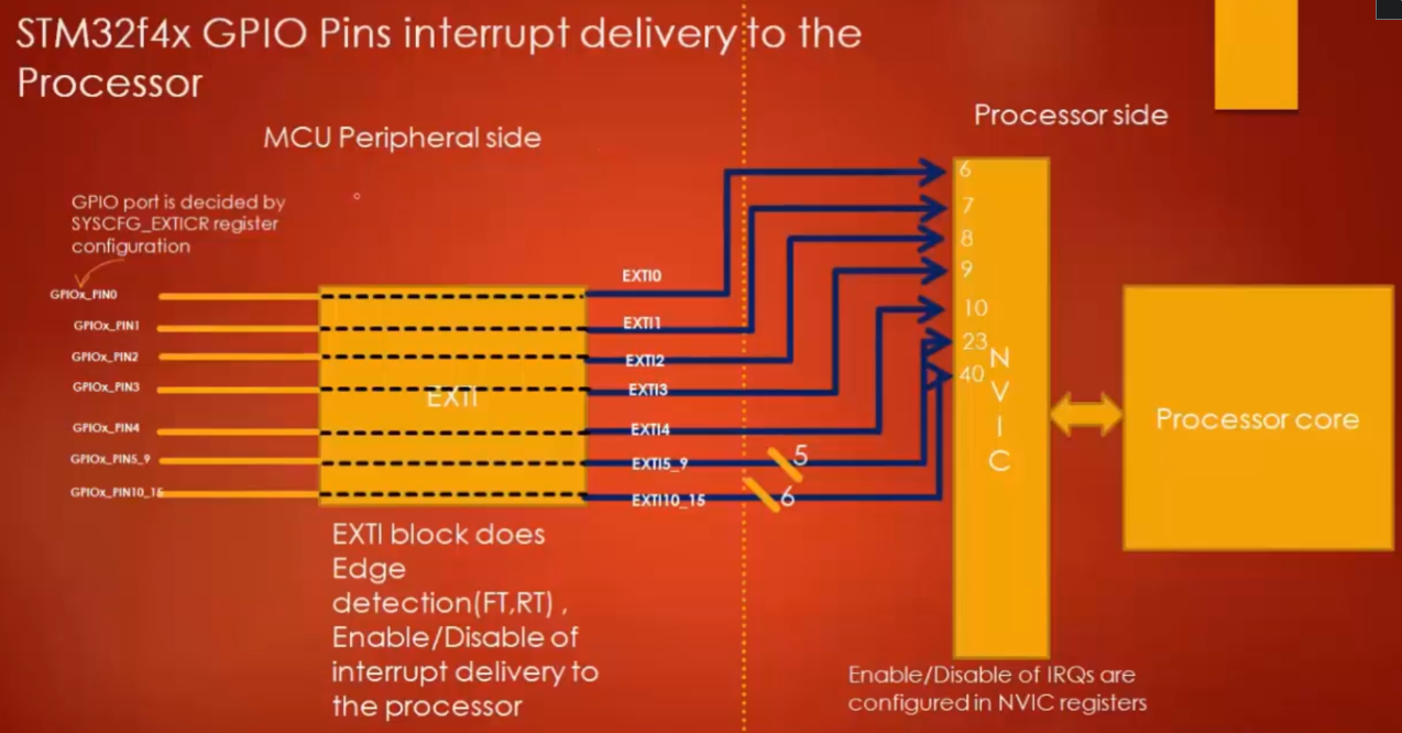
Pinxof all GPIO ports will shareEXTIx. Then how do you assign a specific port to anEXTIxline?By using the SYSCFG_EXTICRregister!By default,
EXTI0will be used byGPIOA Pin0. ConfigureSYSCFG_EXTICRto select which GPIO port to use the EXTI line.
GPIO Interrupt Handling
When an interrupt is received through a GPIO pin, EXTI controller will detected it (Falling-edge, rising-edge, or both) and the corresponding EXTIx line will be triggered. Then, the fixed vector address of the corresponding IRQ number will be accessed. In the memory space fixed vector address points to holds the address of an IRQ handler (or Interrupt Service Routine; ISR) that needs to be invoked.
The lower the IRQ number, the higher the priority.
If another IRQ is triggered while the processor is executing an ISR, their IRQ numbers will be compared, and if the newely arrived register happened to be of higher priority, the currently running ISR will be preempted.
Even if the IRQ is disabled (
ICERxregister), the incoming interrupt will still be pended in the pending register (ISPRx).Implement the ISR, and store its address to the vector address location corresponding to the IRQ number for which the ISR is written.
In fact, ISRs are application specific and therefore should be written in the application layer. The ISRs implemented in the application layer should call the driver supported peripheral handling APIs to service that IRQ.
ISRs are registered in the startup code as
.weakfunctions which will be redirected to theDefault_Handler()until they are defined by the programmer. All you need to do is to implement the ISR with the name found in the startup file. Then, upon invocation, the user-defined ISR will be called instead of theDefault_Handler().