Home | Projects | Notes > MCU Peripheral Drivers > SPI Application 1: Master Only Tx (Blocking) (spi_01_master_only_tx_blocking.c)
SPI Application 1: Master Only Tx (Blocking) (spi_01_master_only_tx_blocking.c)
Requirements
Test the
SPI_TxBlocking)API to send the string "Hello world" with the following configurations:SPI2 - Master mode
SCLK - Max possible
DFF = 0, and DFF = 1
For this application, only MOSI and SCLK pins will be used. (No slave, so MISO, NSS pins are not necessary.) Find out the GPIO pins over which SPI2 can communicate! Look up the "Alternate function mapping" table in the datasheet.
SPI2_SCK
SPI2_MOSI
SPI2_MISO
SPI2_NSS
To analyze the communication with the logic analyzer, connect the channels as follows:
CH0 - SCLK
CH1 - MOSI
Code
spi_01_master_only_tx_blocking.c
Path: Project/Src/
xxxxxxxxxx1381/*******************************************************************************2 * File : spi_01_master_only_tx_blocking.c3 * Brief : Program to test SPI master's Tx (blocking) functionality4 * (without slave)5 * Author : Kyungjae Lee6 * Date : May 27, 20237 ******************************************************************************/8
9/**10 * Pin selection for SPI communication11 *12 * SPI2_SCK - PB13 (AF5)13 * SPI2_MOSI - PB15 (AF5)14 * SPI2_MISO - PB14 (AF5)15 * SPI2_NSS - PB12 (AF5)16 */17
18/* strlen() */19
21/**22 * SPI2_PinsInit()23 * Brief : Initializes and configures GPIO pins to be used as SPI2 pins24 * Param : None25 * Retval : None26 * Note : N/A27 */28void SPI2_PinsInit(void)29{30 GPIO_Handle_TypeDef SPI2Pins;31
32 /* Zero-out all the fields in the structures (Very important! SPI2Pins33 * is a local variables whose members may be filled with garbage values before34 * initialization. These garbage values may set (corrupt) the bit fields that35 * you did not touch assuming that they will be 0 by default. Do NOT make this36 * mistake!37 */38 memset(&SPI2Pins, 0, sizeof(SPI2Pins));39
40 SPI2Pins.pGPIOx = GPIOB;41 SPI2Pins.GPIO_PinConfig.GPIO_PinMode = GPIO_PIN_MODE_ALTFCN;42 SPI2Pins.GPIO_PinConfig.GPIO_PinAltFcnMode = 5;43 SPI2Pins.GPIO_PinConfig.GPIO_PinOutType = GPIO_PIN_OUT_TYPE_PP;44 /* I2C - Open-drain only!, SPI - Push-pull okay! */45 SPI2Pins.GPIO_PinConfig.GPIO_PinPuPdControl = GPIO_PIN_NO_PUPD; /* Optional */46 SPI2Pins.GPIO_PinConfig.GPIO_PinSpeed = GPIO_PIN_OUT_SPEED_HIGH; /* Medium or slow ok as well */47
48 /* SCLK */49 SPI2Pins.GPIO_PinConfig.GPIO_PinNumber = GPIO_PIN_13;50 GPIO_Init(&SPI2Pins);51
52 /* MOSI */53 SPI2Pins.GPIO_PinConfig.GPIO_PinNumber = GPIO_PIN_15;54 GPIO_Init(&SPI2Pins);55
56 /* MISO (Not required for this application, save it for other use) */57 //SPI2Pins.GPIO_PinConfig.GPIO_PinNumber = GPIO_PIN_14;58 //GPIO_Init(&SPI2Pins);59
60 /* NSS (Not required for this application, save it for other use) */61 //SPI2Pins.GPIO_PinConfig.GPIO_PinNumber = GPIO_PIN_12;62 //GPIO_Init(&SPI2Pins);63} /* End of SPI2_PinsInit */64
65/**66 * SPI2_Init()67 * Brief : Creates an SPI2Handle and initializes SPI2 peripheral parameters68 * Param : None69 * Retval : None70 * Note : N/A71 */72void SPI2_Init(void)73{74 SPI_Handle_TypeDef SPI2Handle;75
76 /* Zero-out all the fields in the structures (Very important! SPI2Handle77 * is a local variables whose members may be filled with garbage values before78 * initialization. These garbage values may set (corrupt) the bit fields that79 * you did not touch assuming that they will be 0 by default. Do NOT make this80 * mistake!81 */82 memset(&SPI2Handle, 0, sizeof(SPI2Handle));83
84 SPI2Handle.pSPIx = SPI2;85 SPI2Handle.SPI_Config.SPI_BusConfig = SPI_BUS_CONFIG_FULL_DUPLEX;86 SPI2Handle.SPI_Config.SPI_DeviceMode = SPI_DEVICE_MODE_MASTER;87 SPI2Handle.SPI_Config.SPI_SCLKSpeed = SPI_SCLK_SPEED_PRESCALAR_2; /* Generates 8MHz SCLK */88 /* Min prescalar -> maximum clk speed */89 SPI2Handle.SPI_Config.SPI_DFF = SPI_DFF_8BITS;90 SPI2Handle.SPI_Config.SPI_CPOL = SPI_CPOL_LOW;91 SPI2Handle.SPI_Config.SPI_CPHA = SPI_CPHA_LOW;92 SPI2Handle.SPI_Config.SPI_SSM = SPI_SSM_EN; /* SW slave mgmt enabled for NSS pin since NSS is not used */93
94 SPI_Init(&SPI2Handle);95} /* End of SPI2_Init */96
97
98int main(int argc, char *argv[])99{100 char msg[] = "Hello world"; /* Message to transnmit */101
102 /* Initialize and configure GPIO pins to be used as SPI2 pins */103 SPI2_PinsInit();104
105 /* Initialize SPI2 peripheral parameters */106 SPI2_Init();107 /* At this point, all the required parameters are loaded into SPIx control registers.108 * But, this does not mean that SPI2 peripheral is enabled.109 *110 * SPI configuration must be completed before it is enabled. When SPI is enabled, it111 * will be busy communicating with other device(s) and will not allow modifying its112 * control registers.113 */114
115 /* To make NSS signal pulled to high internally and avoid MODF error */116 SPI_SSIConfig(SPI2, ENABLE);117
118 /* Enable SPI2 peripheral (Set SPI_CR1 bit[6] SPE - Peripheral enabled) */119 SPI_PeriControl(SPI2, ENABLE);120
121 /* Send data */122 SPI_TxBlocking(SPI2, (uint8_t *)msg, strlen(msg));123
124 /* Wait until SPI no longer busy */125 while (SPI2->SR & (0x1 << SPI_SR_BSY));126 /* SPI_SR bit[7] - BSY (Busy flag)127 * 0: SPI (or I2S) not busy128 * 1: SPI (or I2S) is busy in communication or Tx buffer is not empty129 * This flag is set and cleared by hardware.130 */131
132 /* Disable SPI2 peripheral (Terminate communication) */133 SPI_PeriControl(SPI2, DISABLE);134
135 while (1);136
137 return 0;138} /* End of main */
Testing
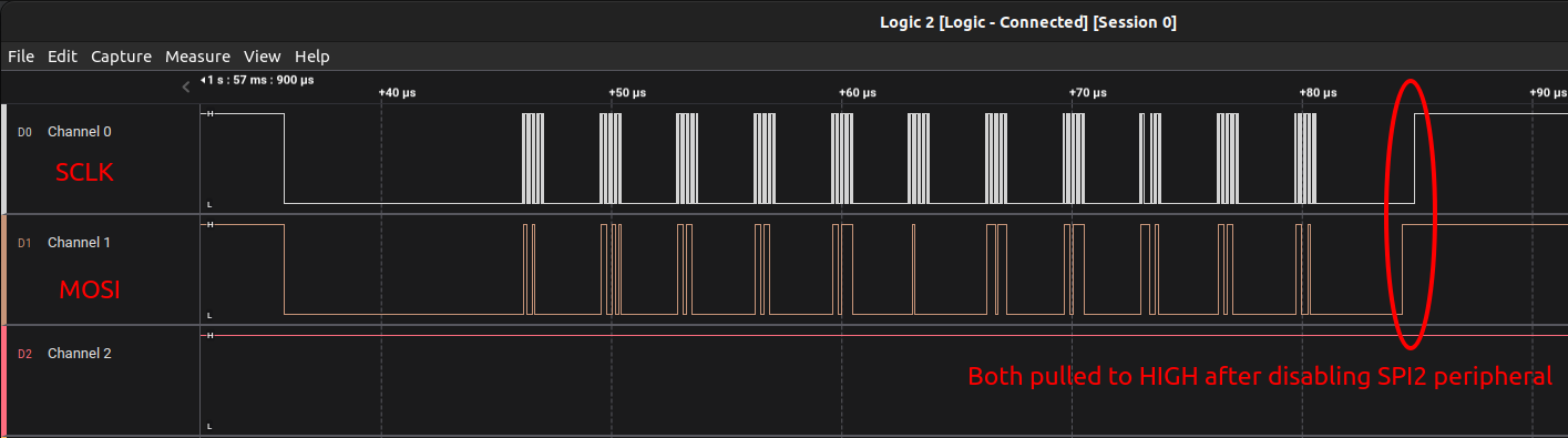
The following snapshots are taken using the Logic Analyzer.
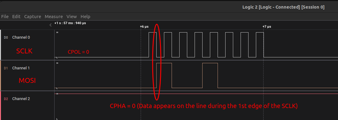
SPI Transmission when CPOL=0, CPHA=0
The following snapshot shows "Hello world" being transferred through MOSI line.
Since CPOL = 0, SCLK begins LOW, and stays LOW during the idle state.
Since CPHA = 0, the data appears on the MOSI line during the 1st edge of the SCLK.
Try different combinations of CPOL and CPHA and monitor the digital waveform.
Note
Here we used SSM (software Slave Management) is enabled. For master, the NSS signal should be tied to +VCC when not used to avoid MODF error which happens in multi-master situation. So, be sure to set SSI bit to pull NSS pin to +VCC internally.
Remember!
SSI bit influences NSS state when SSM = 1. By default, SSI = 0, so NSS will be pulled low which is not acceptable for master when working in non-multi-master situation.