Home | Projects | Notes > MCU Peripheral Drivers > SPI Application 2: Master Tx (Blocking) (spi_02_master_tx_blocking.c)
SPI Application 2: Master Tx (Blocking) (spi_02_master_tx_blocking.c)
Requirements
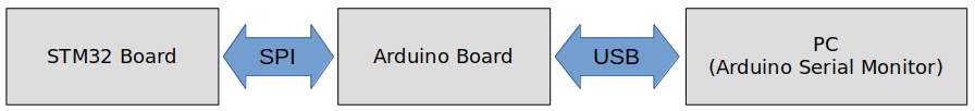
SPI master(STM) and SPI slave(Arduino) communication
When the button on the master is pressed, master shall send a string of data to the slave in connection. The data received by the slave shall be displayed on the slave's serial port.
Requirements
Use SPI full duplex mode
ST board will be in SPI master mode, and Arduino board will be in SPI slave mode.
Use DFF = 0
Use hardware slave management (SSM = 0)
SCLK speed = 500 KHz, fclk = 16MHz
In this application, master is not going to receive anything from the slave. So, configuring the MISO pin is not necessary.
The slave does not know how many bytes of data master is going to send. So, the master must first send the number of bytes the slave should expect to receive.
Parts Needed
Arduino board
STM32 board
Logic level converter
Breadboard and jumper wires
STM32 Board and Arduino Board Communication Interfaces
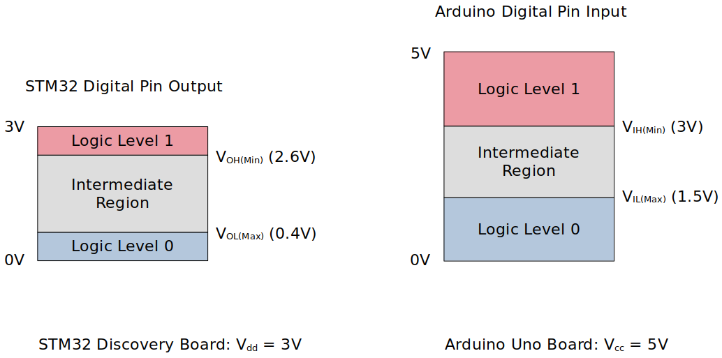
STM32 Board and Arduino Board Voltage Levels
To work around the voltage level difference, a logic level shifter will be necessary.
Setup
1. Find out the GPIO pins that can be used for SPI2 communication
For this application, MOSI, SCK and NSS pins will be used. Find out the GPIO pins over which SPI2 can communicate! Look up the "Alternate function mapping" table in the datasheet.
SPI2_MOSI
SPI2_SCK
SPI2_MISO
SPI2_NSS
2. Connect STM32 Discovery board with Arduino Uno board SPI pins
Be careful not to directly supply 5 volts to the STM32 board pins when the board is not powered up as they may be damaged. When the logic level shifter is used, you don't need to worry about this issue.

To analyze the communication with the logic analyzer, connect the channels as follows:
CH0 - SCLK
CH1 - MOSI
CH2 - MISO
CH3 - NSS
GND - Common GND of the bread board
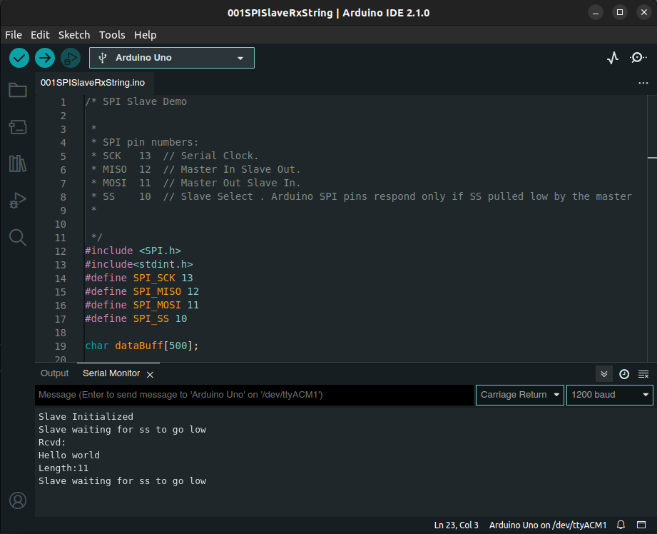
3. Power Arduino board and upload SPI slave sketch to Arduino
Sketch name:
001SPISlaveRxString.inoAs soon as you download this sketch to the Arduino board, it will operate as a slave.
Code
spi_02_master_tx_blocking.c
Path: Project/Src/
xxxxxxxxxx2001/*******************************************************************************2 * File : spi_02_master_tx_blocking.c3 * Brief : Program to test SPI master's Tx (blocking) functionality4 * (with slave)5 * Author : Kyungjae Lee6 * Date : Jun 02, 20237 ******************************************************************************/8
9/**10 * Pin selection for SPI communication11 *12 * SPI2_SCK - PB13 (AF5)13 * SPI2_MOSI - PB15 (AF5)14 * SPI2_MISO - PB14 (AF5)15 * SPI2_NSS - PB12 (AF5)16 */17
18/* strlen() */19
21/**22 * delay()23 * Brief : Spinlock delays the program execution24 * Param : None25 * Retval : None26 * Note : N/A27 */28void delay(void)29{30 /* Appoximately ~200ms delay when the system clock freq is 16 MHz */31 for (uint32_t i = 0; i < 500000 / 2; i++);32} /* End of Delay */33
34/**35 * SPI2_PinsInit()36 * Brief : Initializes and configures GPIO pins to be used as SPI2 pins37 * Param : None38 * Retval : None39 * Note : N/A40 */41void SPI2_PinsInit(void)42{43 GPIO_Handle_TypeDef SPI2Pins;44
45 /* Zero-out all the fields in the structures (Very important! SPI2Pins46 * is a local variables whose members may be filled with garbage values before47 * initialization. These garbage values may set (corrupt) the bit fields that48 * you did not touch assuming that they will be 0 by default. Do NOT make this49 * mistake!50 */51 memset(&SPI2Pins, 0, sizeof(SPI2Pins));52
53 SPI2Pins.pGPIOx = GPIOB;54 SPI2Pins.GPIO_PinConfig.GPIO_PinMode = GPIO_PIN_MODE_ALTFCN;55 SPI2Pins.GPIO_PinConfig.GPIO_PinAltFcnMode = 5;56 SPI2Pins.GPIO_PinConfig.GPIO_PinOutType = GPIO_PIN_OUT_TYPE_PP;57 /* I2C - Open-drain only!, SPI - Push-pull okay! */58 SPI2Pins.GPIO_PinConfig.GPIO_PinPuPdControl = GPIO_PIN_NO_PUPD; /* Optional */59 SPI2Pins.GPIO_PinConfig.GPIO_PinSpeed = GPIO_PIN_OUT_SPEED_HIGH; /* Medium or slow ok as well */60
61 /* SCLK */62 SPI2Pins.GPIO_PinConfig.GPIO_PinNumber = GPIO_PIN_13;63 GPIO_Init(&SPI2Pins);64
65 /* MOSI */66 SPI2Pins.GPIO_PinConfig.GPIO_PinNumber = GPIO_PIN_15;67 GPIO_Init(&SPI2Pins);68
69 /* MISO (Not required for this application, save it for other use) */70 //SPI2Pins.GPIO_PinConfig.GPIO_PinNumber = GPIO_PIN_14;71 //GPIO_Init(&SPI2Pins);72
73 /* NSS */74 SPI2Pins.GPIO_PinConfig.GPIO_PinNumber = GPIO_PIN_12;75 GPIO_Init(&SPI2Pins);76} /* End of SPI2_PinsInit */77
78/**79 * SPI2_Init()80 * Brief : Creates an SPI2Handle and initializes SPI2 peripheral parameters81 * Param : None82 * Retval : None83 * Note : N/A84 */85void SPI2_Init(void)86{87 SPI_Handle_TypeDef SPI2Handle;88
89 /* Zero-out all the fields in the structures (Very important! SPI2Handle90 * is a local variables whose members may be filled with garbage values before91 * initialization. These garbage values may set (corrupt) the bit fields that92 * you did not touch assuming that they will be 0 by default. Do NOT make this93 * mistake!94 */95 memset(&SPI2Handle, 0, sizeof(SPI2Handle));96
97 SPI2Handle.pSPIx = SPI2;98 SPI2Handle.SPI_Config.SPI_BusConfig = SPI_BUS_CONFIG_FULL_DUPLEX;99 SPI2Handle.SPI_Config.SPI_DeviceMode = SPI_DEVICE_MODE_MASTER;100 SPI2Handle.SPI_Config.SPI_SCLKSpeed = SPI_SCLK_SPEED_PRESCALAR_32; /* Generates 500KHz SCLK */101 /* Min prescalar -> maximum clk speed */102 SPI2Handle.SPI_Config.SPI_DFF = SPI_DFF_8BITS;103 SPI2Handle.SPI_Config.SPI_CPOL = SPI_CPOL_LOW;104 SPI2Handle.SPI_Config.SPI_CPHA = SPI_CPHA_LOW;105 SPI2Handle.SPI_Config.SPI_SSM = SPI_SSM_DI; /* HW slave mgmt enabled (SSM = 0) for NSS pin */106
107 SPI_Init(&SPI2Handle);108} /* End of SPI2_Init */109
110/**111 * GPIO_ButtonInit()112 * Brief : Initializes a GPIO pin for button113 * Param : None114 * Retval : None115 * Note : N/A116 */117void GPIO_ButtonInit(void)118{119 GPIO_Handle_TypeDef GPIOBtn;120
121 /* Zero-out all the fields in the structures (Very important! GPIOBtn122 * is a local variables whose members may be filled with garbage values before123 * initialization. These garbage values may set (corrupt) the bit fields that124 * you did not touch assuming that they will be 0 by default. Do NOT make this125 * mistake!126 */127 memset(&GPIOBtn, 0, sizeof(GPIOBtn));128
129 /* GPIOBtn configuration */130 GPIOBtn.pGPIOx = GPIOA;131 GPIOBtn.GPIO_PinConfig.GPIO_PinNumber = GPIO_PIN_0;132 GPIOBtn.GPIO_PinConfig.GPIO_PinMode = GPIO_PIN_MODE_IN;133 GPIOBtn.GPIO_PinConfig.GPIO_PinSpeed = GPIO_PIN_OUT_SPEED_HIGH; /* Doesn't matter */134 //GPIOBtn.GPIO_PinConfig.GPIO_PinOutType = GPIO_PIN_OUT_TYPE_PP; /* N/A */135 GPIOBtn.GPIO_PinConfig.GPIO_PinPuPdControl = GPIO_PIN_NO_PUPD;136 /* External pull-down resistor is already present (see the schematic) */137 GPIO_Init(&GPIOBtn);138} /* End of GPIO_ButtonInit */139
140
141int main(int argc, char *argv[])142{143 char msg[] = "Hello world";144
145 /* Initialize and configure GPIO pin for user button */146 GPIO_ButtonInit();147
148 /* Initialize and configure GPIO pins to be used as SPI2 pins */149 SPI2_PinsInit();150
151 /* Initialize SPI2 peripheral parameters */152 SPI2_Init();153 /* At this point, all the required parameters are loaded into SPIx control registers.154 * But, this does not mean that SPI2 peripheral is enabled.155 *156 * SPI configuration must be completed before it is enabled. When SPI is enabled, it157 * will be busy communicating with other device(s) and will not allow modifying its158 * control registers.159 */160
161 /* Enable NSS output (Set SPI_CR2 bit[2] SSOE - Slave Select Output Enable) */162 SPI_SSOEConfig(SPI2, ENABLE);163 /* Setting SSOE bit to 1 enables the NSS output.164 * The NSS pin is automatically managed by the hardware.165 * i.e., When SPE = 1, NSS will be pulled to low, and when SPE = 0, NSS will be166 * pulled to high.167 */168
169 while (1)170 {171 /* Wait until button is pressed */172 while (!GPIO_ReadFromInputPin(GPIOA, GPIO_PIN_0));173
174 /* Introduce debouncing time for button press */175 delay();176
177 /* Enable SPI2 peripheral (Set SPI_CR1 bit[6] SPE - Peripheral enabled) */178 SPI_PeriControl(SPI2, ENABLE);179
180 /* Arduino sketch expects 1 byte of length information followed by data */181 /* Send length information to the slave first */182 uint8_t msgLen = strlen(msg);183 SPI_TxBlocking(SPI2, &msgLen, 1);184 /* Send data */185 SPI_TxBlocking(SPI2, (uint8_t *)msg, strlen(msg));186
187 /* Wait until SPI no longer busy */188 while (SPI2->SR & (0x1 << SPI_SR_BSY));189 /* SPI_SR bit[7] - BSY (Busy flag)190 * 0: SPI (or I2S) not busy191 * 1: SPI (or I2S) is busy in communication or Tx buffer is not empty192 * This flag is set and cleared by hardware.193 */194
195 /* Disable SPI2 peripheral (Terminate communication) */196 SPI_PeriControl(SPI2, DISABLE);197 }198
199 return 0;200} /* End of main */The master's clock frequency has been adjusted from 2 MHz (prescalar = 8) to 500 KHz (prescalar = 32) to be compatible with the baudrate (1200) of the slave.
Arduino Sketch (001SPISlaveRxString.ino)
xxxxxxxxxx881/* SPI Slave Demo2
3 *4 * SPI pin numbers:5 * SCK 13 // Serial Clock.6 * MISO 12 // Master In Slave Out.7 * MOSI 11 // Master Out Slave In.8 * SS 10 // Slave Select . Arduino SPI pins respond only if SS pulled low by the master9 *10 11 */12
19char dataBuff[500];20
21//Initialize SPI slave.22void SPI_SlaveInit(void) 23{ 24 // Initialize SPI pins.25 pinMode(SCK, INPUT);26 pinMode(MOSI, INPUT);27 pinMode(MISO, OUTPUT);28 pinMode(SS, INPUT);29 //make SPI as slave30 31 // Enable SPI as slave.32 SPCR = (1 << SPE);33}34
35//This function returns SPDR Contents 36uint8_t SPI_SlaveReceive(void)37{38 /* Wait for reception complete */39 while(!(SPSR & (1<<SPIF)));40 /* Return Data Register */41 return SPDR;42}43
44
45//sends one byte of data 46void SPI_SlaveTransmit(char data)47{48 /* Start transmission */49 SPDR = data;50 /* Wait for transmission complete */51 while(!(SPSR & (1<<SPIF)));52}53 54
55// The setup() function runs right after reset.56void setup() 57{58 // Initialize serial communication 59 Serial.begin(1200);60 // Initialize SPI Slave.61 SPI_SlaveInit();62 Serial.println("Slave Initialized");63}64
65// The loop function runs continuously after setup().66void loop() 67{68 uint32_t i;69 uint16_t dataLen = 0;70 Serial.println("Slave waiting for ss to go low");71 while(digitalRead(SS));72
73 i = 0;74 dataLen = SPI_SlaveReceive();75 for(i = 0 ; i < dataLen ; i++ )76 {77 dataBuff[i] = SPI_SlaveReceive();78 }79
80
81 // Serial.println(String(i,HEX));82 dataBuff[i] = '\0';83 84 Serial.println("Rcvd:");85 Serial.println(dataBuff);86 Serial.print("Length:");87 Serial.println(dataLen);88}Original baudrate (9600) has been changed to 1200 since the communication didn't work with the original baudrate. (In the STM32 application, the master's clock frequency has been adjusted from 2 MHz to 500 KHz accordingly.)
Testing
The following snapshots are taken using the Logic Analyzer.
Entire Communication
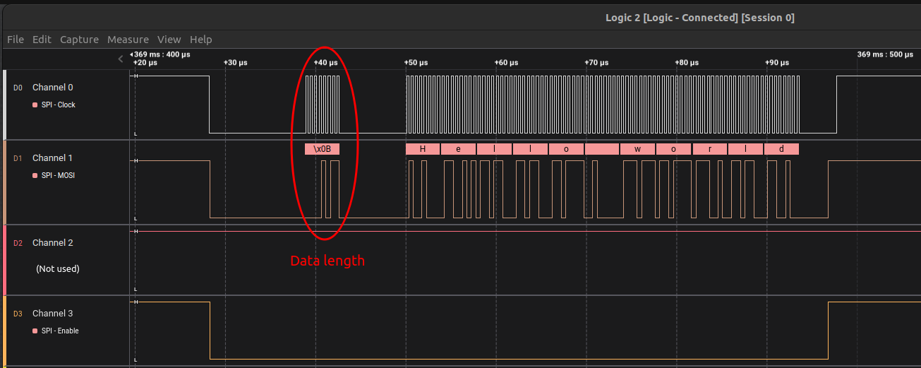
Notice that as soon as
SPEis set to 0,NSSis pulled to GND (LOW), and as soon asSPEis set to 1,NSSis pulled to HIGH automatically by the hardware.
Although data was successfully sent out by the STM32 Discovery board (as shown in the snapshot above), the Arduino Uno R3 board didn't seem to receive the data.
SPI pins of the STM32 board was set to 2MHz, and Arduino board serial monitor baudrate was set to 9600.
Test and debug this application again!
Arduino IDE Serial Monitor