Home | Projects | Notes > MCU Peripheral Drivers > SPI Application 4: Master Rx (Interrupt) (spi_04_master_rx_interrupt)
SPI Application 4: Master-Slave Rx (Interrupt) (spi_04_master_rx_interrupt)
Requirements
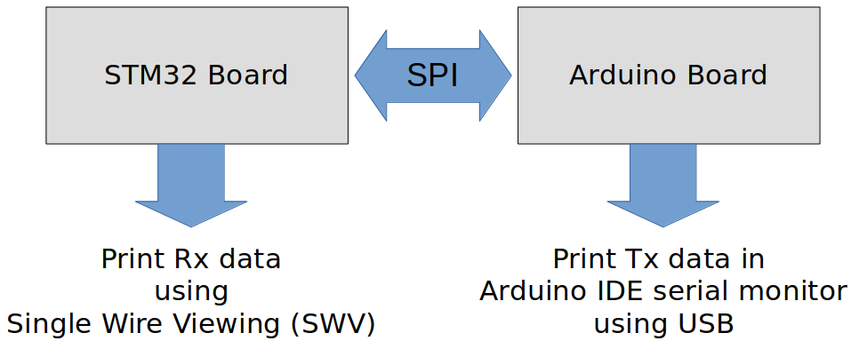
STM32 Discovery board (master) receives the message from the Arduino board (slave) over SPI.
User enters the message using Arduino serial monitor terminal
Arduino board notifies the STM32 board about message availability
STM32 board reads and prints the message
Requirements
Use SPI full duplex mode
ST board will be in SPI master mode, and Arduino board will be in SPI slave mode.
Use DFF = 0
Use hardware slave management (SSM = 0)
SCLK speed = 500 KHz, fclk = 16MHz
Parts Needed
Arduino board
STM32 board
Logic level converter
Breadboard and jumper wires
STM32 Board and Arduino Board Communication Interfaces
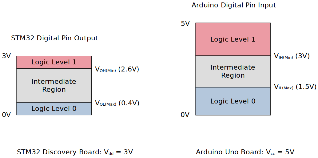
STM32 Board and Arduino Board Voltage Levels
To work around the voltage level difference, a logic level shifter will be necessary.
Setup
1. Find out the GPIO pins that can be used for SPI2 communication
For this application, all four SPI communication lines (i.e., MOSI, MISO, SCK and NSS pins) will be used. Find out the GPIO pins over which SPI2 can communicate! Look up the "Alternate function mapping" table in the datasheet.
SPI2_MOSI
SPI2_SCK
SPI2_MISO
SPI2_NSS
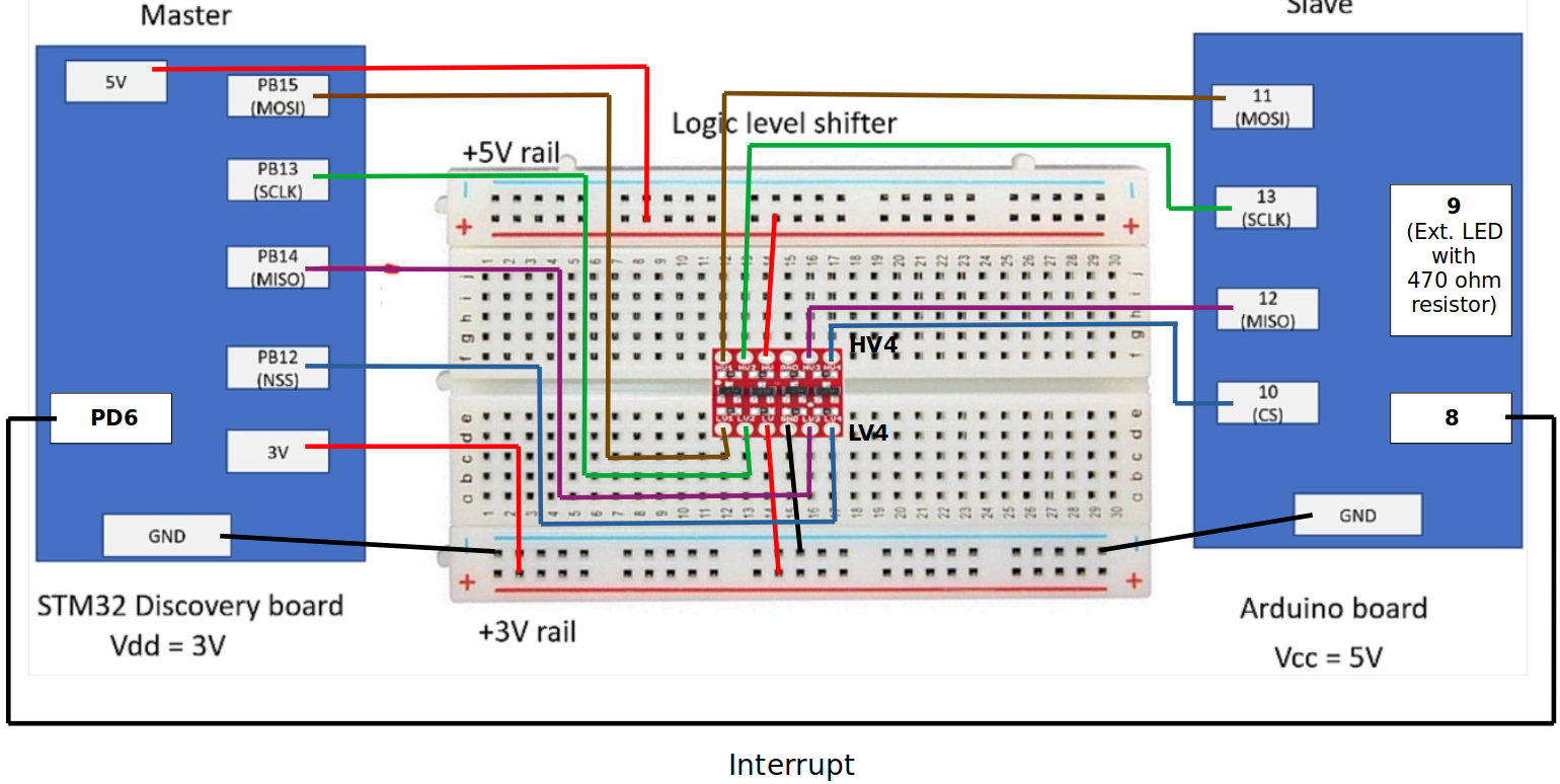
2. Connect STM32 Discovery board with Arduino Uno board SPI pins
Pin connection is basically the same as that of the SPI Application 3's. Just an interrupt line is added between the pin
PD6of the STM32 board and8of the Arduino board.Arduino board pin
8will transition from HIGH to LOW whenever a message (entered by user through Arduino serial monitor) is availablen and this will trigger an interrupt through STM32 board's pinPD6to notify the master of the message ready for read.Master will then generate clock signal to read the data.
Be careful not to directly supply 5 volts to the STM32 board pins when the board is not powered up as they may be damaged. When the logic level shifter is used, you don't need to worry about this issue.
To analyze the communication with the logic analyzer, connect the channels as follows:
CH0 - SCLK
CH1 - MOSI
CH2 - MISO
CH3 - NSS
GND - Common GND of the bread board
3. Power Arduino board and upload SPI slave sketch to Arduino
Sketch name:
003SPISlaveUartReadOverSPI.inoAs soon as you download this sketch to the Arduino board, it will operate as a slave.
Code
spi_04_master_rx_interrupt.c
Path: Project/Src/
xxxxxxxxxx2911/*******************************************************************************2 * File : spi_04_master_rx_interrupt.c3 * Brief : Program to demonstrate receiving and printing the user message4 * received from the Arduino peripheral in SPI interrupt mode.5 * User sends the message through Arduino IDE's serial monitor tool.6 * Monitor the message received using the SWV ITM data console of7 * STM32CubeIDE.8 * Author : Kyungjae Lee9 * Date : Jun 06, 202310 *11 * Note : Follow the instruction s to test this code.12 * 1. Download this code to the STM32 board (master)13 * 2. Download slave code (003SPISlaveUartReadOverSPI.ino) to14 * the Arduino board (slave)15 * 3. Reset both boards16 * 4. Enable SWV ITM data console to see the message17 * 5. Open Arduino IDE serial monitor tool18 * 6. Type anything and send the message (Make sure to set the19 * line ending to 'carriage return'.)20 ******************************************************************************/21
22/**23 * Pin selection for SPI communication24 *25 * SPI2_NSS - PB12 (AF5)26 * SPI2_SCK - PB13 (AF5)27 * SPI2_MISO - PB14 (AF5)28 * SPI2_MOSI - PB15 (AF5)29 */30
31/* printf() */32/* strlen() */33
35
37/* Global variables */38SPI_Handle_TypeDef SPI2Handle;39char rxBuf[MAX_LEN];40volatile uint8_t rxByte;41volatile uint8_t rxStop = 0;42 /* Declare it as 'volatile' since it gets modified in the43 * 'SPI_ApplicationEventCallback()' function, which runs in the44 * 'SPI2_IRQHander''s context45 */46volatile uint8_t dataAvailable = 0;47 /* This flag will be set in the interrupt handler of the Arduino interrupt GPIO48 * (Since it gets modified inside the ISR, declare it as 'volatile')49 */50
51/**52 * delay()53 * Brief : Spinlock delays the program execution54 * Param : None55 * Retval : None56 * Note : N/A57 */58void delay(void)59{60 /* Appoximately ~200ms delay when the system clock freq is 16 MHz */61 for (uint32_t i = 0; i < 500000 / 2; i++);62} /* End of Delay */63
64/**65 * SPI2_PinsInit()66 * Brief : Initializes and configures GPIO pins to be used as SPI2 pins67 * Param : None68 * Retval : None69 * Note : N/A70 */71void SPI2_PinsInit(void)72{73 GPIO_Handle_TypeDef SPI2Pins;74
75 /* Zero-out all the fields in the structures (Very important! SPI2Pins76 * is a local variables whose members may be filled with garbage values before77 * initialization. These garbage values may set (corrupt) the bit fields that78 * you did not touch assuming that they will be 0 by default. Do NOT make this79 * mistake!80 */81 memset(&SPI2Pins, 0, sizeof(SPI2Pins));82
83 SPI2Pins.pGPIOx = GPIOB;84 SPI2Pins.GPIO_PinConfig.GPIO_PinMode = GPIO_PIN_MODE_ALTFCN;85 SPI2Pins.GPIO_PinConfig.GPIO_PinAltFcnMode = 5;86 SPI2Pins.GPIO_PinConfig.GPIO_PinOutType = GPIO_PIN_OUT_TYPE_PP;87 /* I2C - Open-drain only!, SPI - Push-pull okay! */88 SPI2Pins.GPIO_PinConfig.GPIO_PinPuPdControl = GPIO_PIN_NO_PUPD; /* Optional */89 SPI2Pins.GPIO_PinConfig.GPIO_PinSpeed = GPIO_PIN_OUT_SPEED_HIGH; /* Medium or slow ok as well */90
91 /* SCLK */92 SPI2Pins.GPIO_PinConfig.GPIO_PinNumber = GPIO_PIN_13;93 GPIO_Init(&SPI2Pins);94
95 /* MOSI */96 SPI2Pins.GPIO_PinConfig.GPIO_PinNumber = GPIO_PIN_15;97 GPIO_Init(&SPI2Pins);98
99 /* MISO */100 SPI2Pins.GPIO_PinConfig.GPIO_PinNumber = GPIO_PIN_14;101 GPIO_Init(&SPI2Pins);102
103 /* NSS */104 SPI2Pins.GPIO_PinConfig.GPIO_PinNumber = GPIO_PIN_12;105 GPIO_Init(&SPI2Pins);106} /* End of SPI2_PinsInit */107
108/**109 * SPI2_Init()110 * Brief : Creates an SPI2Handle and initializes SPI2 peripheral parameters111 * Param : None112 * Retval : None113 * Note : N/A114 */115void SPI2_Init(void)116{117 SPI2Handle.pSPIx = SPI2;118 SPI2Handle.SPI_Config.SPI_BusConfig = SPI_BUS_CONFIG_FULL_DUPLEX;119 SPI2Handle.SPI_Config.SPI_DeviceMode = SPI_DEVICE_MODE_MASTER;120 SPI2Handle.SPI_Config.SPI_SCLKSpeed = SPI_SCLK_SPEED_PRESCALAR_32; /* Generates 500KHz SCLK */121 /* Min prescalar -> maximum clk speed */122 SPI2Handle.SPI_Config.SPI_DFF = SPI_DFF_8BITS;123 SPI2Handle.SPI_Config.SPI_CPOL = SPI_CPOL_LOW;124 SPI2Handle.SPI_Config.SPI_CPHA = SPI_CPHA_LOW;125 SPI2Handle.SPI_Config.SPI_SSM = SPI_SSM_DI; /* HW slave mgmt enabled (SSM = 0) for NSS pin */126
127 SPI_Init(&SPI2Handle);128} /* End of SPI2_Init */129
130/**131 * SPI2_IntPinInit()132 * Brief : Configures the GPIO pin (PD6) over which SPI peripheral issues133 * 'data available' interrupt134 * Param : None135 * Retval : None136 * Note : N/A137 */138void SPI2_IntPinInit(void)139{140 GPIO_Handle_TypeDef SPIIntPin;141 memset(&SPIIntPin, 0, sizeof(SPIIntPin));142
143 /* GPIO pin (for interrupt) configuration */144 SPIIntPin.pGPIOx = GPIOD;145 SPIIntPin.GPIO_PinConfig.GPIO_PinNumber = GPIO_PIN_6;146 SPIIntPin.GPIO_PinConfig.GPIO_PinMode = GPIO_PIN_MODE_IT_FT;147 SPIIntPin.GPIO_PinConfig.GPIO_PinSpeed = GPIO_PIN_OUT_SPEED_LOW;148 SPIIntPin.GPIO_PinConfig.GPIO_PinPuPdControl = GPIO_PIN_PU;149
150 GPIO_Init(&SPIIntPin);151
152 GPIO_IRQPriorityConfig(IRQ_NO_EXTI9_5, NVIC_IRQ_PRI15);153 GPIO_IRQInterruptConfig(IRQ_NO_EXTI9_5, ENABLE);154} /* End of SPI2_IntPinInit */155
156
157int main(int argc, char *argv[])158{159 uint8_t dummyWrite = 0xFF;160
161 printf("Application is running...\n");162
163 /* Initialize and configure GPIO pin for SPI Rx interrupt */164 SPI2_IntPinInit();165
166 /* Initialize and configure GPIO pins to be used as SPI2 pins */167 SPI2_PinsInit();168
169 /* Initialize SPI2 peripheral parameters */170 SPI2_Init();171 /* At this point, all the required parameters are loaded into SPIx control registers.172 * But, this does not mean that SPI2 peripheral is enabled.173 *174 * SPI configuration must be completed before it is enabled. When SPI is enabled, it175 * will be busy communicating with other device(s) and will not allow modifying its176 * control registers.177 */178
179 /* Enable NSS output (Set SPI_CR2 bit[2] SSOE - Slave Select Output Enable) */180 SPI_SSOEConfig(SPI2, ENABLE);181 /* Setting SSOE bit to 1 enables the NSS output.182 * The NSS pin is automatically managed by the hardware.183 * i.e., When SPE = 1, NSS will be pulled to low, and when SPE = 0, NSS will be184 * pulled to high.185 */186
187 /* Enable interrupt for SPI2 peripheral */188 SPI_IRQInterruptConfig(IRQ_NO_SPI2, ENABLE);189
190 while (1)191 {192 rxStop = 0;193
194 /* Wait until 'data available' interrupt is triggered by the transmitter (slave) */195 while (!dataAvailable);196
197 /* Until the master completes reading in the data available, it disables further198 * Rx interrupt from the slave device.199 */200 GPIO_IRQInterruptConfig(IRQ_NO_EXTI9_5, DISABLE);201
202 /* Enable SPI2 peripheral */203 SPI_PeriControl(SPI2, ENABLE);204
205 while (!rxStop)206 {207 /* Read the data from the SPI2 peripheral byte-by-byte in interrupt mode */208 while (SPI_TxInterrupt(&SPI2Handle, &dummyWrite, 1) == SPI_BUSY_IN_TX);209 while (SPI_RxInterrupt(&SPI2Handle, &rxByte, 1) == SPI_BUSY_IN_RX);210
211 /* Note: Master does not have the length information. This process will212 * go on and on until the 'dataAvailable' flag is set back to 0.213 */214 }215
216 /* Wait until SPI no longer busy */217 while (SPI2->SR & (0x1 << SPI_SR_BSY));218 /* SPI_SR bit[7] - BSY (Busy flag)219 * 0: SPI (or I2S) not busy220 * 1: SPI (or I2S) is busy in communication or Tx buffer is not empty221 * This flag is set and cleared by hardware.222 */223
224 /* Disable SPI2 peripheral (Terminate communication) */225 SPI_PeriControl(SPI2, DISABLE);226
227 /* Print the received message to the SWV ITM data console */228 printf("Rx data = %s\n", rxBuf);229
230 /* Reset the 'dataAvailable' flag */231 dataAvailable = 0;232
233 /* Enable back the interrupt for Rx notification from the slave */234 GPIO_IRQInterruptConfig(IRQ_NO_EXTI9_5, ENABLE);235 }236
237 return 0;238} /* End of main */239
240/**241 * SPI2_IRQHandler()242 * Brief : Handles SPI2 interrupt (by calling 'SPI_IRQHandling()')243 * Param : None244 * Retval : None245 * Note : N/A246 */247void SPI2_IRQHandler(void)248{249 SPI_IRQHandling(&SPI2Handle);250} /* End of SPI2_IRQHandler */251
252/**253 * EXTI9_5_IRQHandler()254 * Brief : Handles EXTI IRQ 5 to 9 (by calling 'GPIO_IRQHandling()')255 * Param : None256 * Retval : None257 * Note : N/A258 */259void EXTI9_5_IRQHandler(void)260{261 GPIO_IRQHandling(GPIO_PIN_6);262 dataAvailable = 1;263} /* End of EXTI9_5_IRQHandler */264
265/**266 * SPI_ApplicationEventCallback()267 * Brief : Notifies the application of the event occurred268 * Param : @pSPIHandle - pointer to SPI handle structure269 * @appEvent - SPI event occurred270 * Retval : None271 * Note : N/A272 */273void SPI_ApplicationEventCallback(SPI_Handle_TypeDef *pSPIHandle, uint8_t appEvent)274{275 static uint32_t i = 0;276
277 /* Upon the Rx complete event, copy the data into Rx buffer.278 * '\0' indicates end of message (rxStop = 1)279 */280 if (appEvent == SPI_EVENT_RX_CMPLT)281 {282 rxBuf[i++] = rxByte;283
284 if (rxByte == '\0' || (i == MAX_LEN))285 {286 rxStop = 1;287 rxBuf[i - 1] = '\0'; /* Mark the end of the message with '\0' */288 i = 0;289 }290 }291} /* End of SPI_ApplicationEventCallback */The master's clock frequency has been adjusted from 2 MHz (prescalar = 8) to 500 KHz (prescalar = 32) to be compatible with the baudrate (1200) of the slave.
FYI using 500 KHz for the master and 9600 bps for slave also worked.
Arduino Sketch (003SPISlaveUartReadOverSPI.ino)
xxxxxxxxxx991
3
5bool msgComplete = false; // whether the string is complete6uint8_t userBuffer[MAX_LEN];7uint32_t cnt = 0;8
9//Initialize SPI slave.10void SPI_SlaveInit(void) 11{ 12 // Initialize SPI pins.13 pinMode(SCK, INPUT);14 pinMode(MOSI, INPUT);15 pinMode(MISO, OUTPUT);16 pinMode(SS, INPUT);17 // Enable SPI as slave.18 SPCR = (1 << SPE);19}20
21//This function returns SPDR Contents 22uint8_t SPI_SlaveReceive(void)23{24 /* Wait for reception complete */25 while(!(SPSR & (1<<SPIF)));26 /* Return Data Register */27 return SPDR;28}29
30
31//sends one byte of data 32void SPI_SlaveTransmit(uint8_t data)33{34 /* Start transmission */35 SPDR = data;36 37 /* Wait for transmission complete */38 while(!(SPSR & (1<<SPIF)));39}40 41void setup() 42{43 // Initialize serial for troubleshooting.44 Serial.begin(1200);45 46 // Initialize SPI Slave.47 SPI_SlaveInit();48
49 pinMode(8, INPUT_PULLUP);50 //digitalWrite(8,LOW);51
52 Serial.println("Slave Initialized");53}54
55void notify_controller(void)56{57 pinMode(8,OUTPUT);58 digitalWrite(8,HIGH);59 delayMicroseconds(50);60 digitalWrite(8,LOW);61}62
63
64void loop() {65 66 Serial.println("Type anything and send...");67
68 while(!msgComplete){69 if (Serial.available()) {70 //Read a byte of incoming serial data.71 char readByte = (char)Serial.read();72 //Accumalate in to the buffer73 userBuffer[cnt++] = readByte;74 if(readByte == '\r' || ( cnt == MAX_LEN)){75 msgComplete = true;76 userBuffer[cnt -1 ] = '\0'; //replace '\r' by '\0'77 }78 }79 }80 81 Serial.println("Your message...");82 Serial.println((char*)userBuffer);83
84 85 notify_controller();86
87 /*Transmit the user buffer over SPI */88 for(uint32_t i = 0 ; i < cnt ; i++)89 {90 SPI_SlaveTransmit(userBuffer[i]);91 }92 cnt = 0;93 msgComplete = false;94 Serial.println("Message sent...");95
96 while(!digitalRead(SS));97 Serial.println("Master ends communication");98 99}Original baudrate (9600) has been changed to 1200 since the communication didn't work with the original baudrate. (In the STM32 application, the master's clock frequency has been adjusted from 2 MHz to 500 KHz accordingly.)
FYI using 500 KHz for the master and 9600 bps for slave also worked.
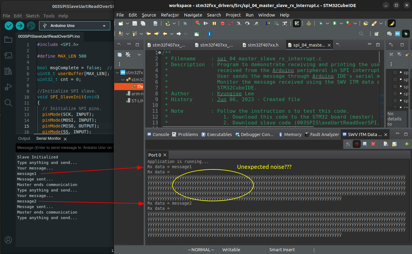
Testing
Debugging required! Master and slave are able to communicate with each other but some noise kicks in as shown in the snapshot below.