Home | Projects | Notes > MCU Peripheral Drivers > I2C Application 3: Master Rx (Interrupt) (i2c_03_master_rx_interrupt.c)
I2C Application 3: Master Rx (Interrupt) (i2c_03_master_rx_interrupt.c)
Requirements
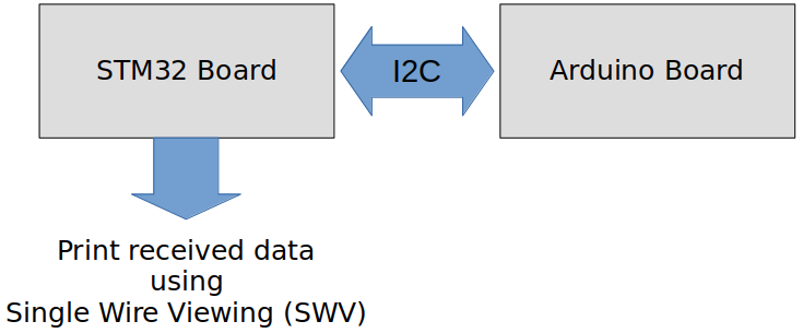
I2C master (STM32 Discovery board) and I2C slave (Arduino board) communication.
When the button on the STM32 board (master) is pressed, the master shall read and display data from the Arduino board (slave). First, the master has to get the length of the data from the slave for it to properly read all data from the slave.
Use I2C SCL = 100 kHz (i.e., standard mode)
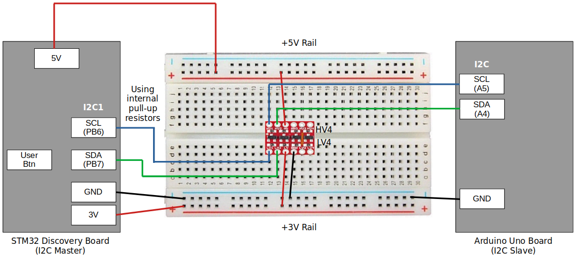
Use internal pull-up resistors for SDA and SCL line
[!] Note: 3.3 kΩ or 4.7 kΩ external pull-up resistors will be necessary in case your MCU pins do not support internal pull-up resistors.
Parts Needed
Arduino board
STM32 board
Logic level converter
Breadboard and jumper wires
STM32 Board and Arduino Board Communication Interfaces
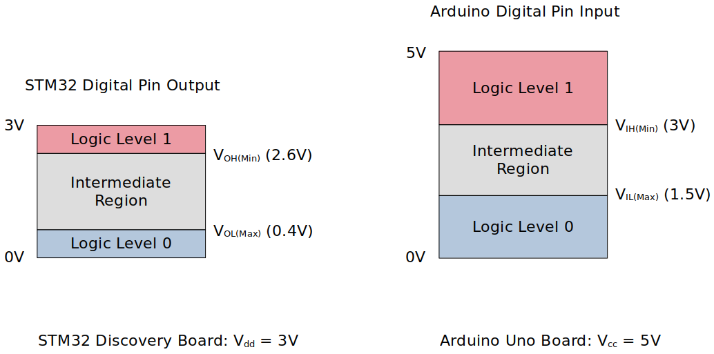
STM32 Board and Arduino Board Voltage Levels
To work around the voltage level difference, a logic level shifter will be necessary.
Procedure to Read Data from Slave (Arduino)
Master sends command code 0x51 to read the 1 byte of length information from the slave.
Master sends command code 0x52 to read the complete data from the slave. (Reading byte-by-byte based on the length information fetched in Step 1)
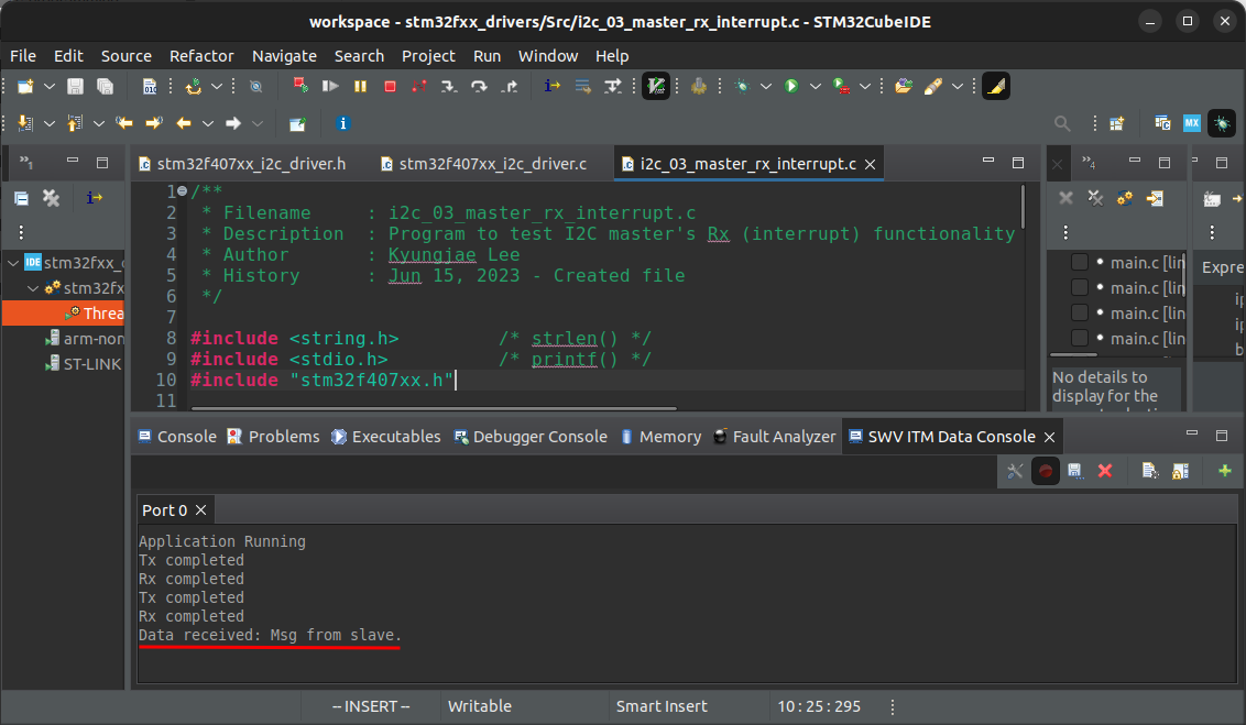
(Master displays the received data using semihosting.)
Using printf() to Print Messages in STM32CubeIDE Console
Setup
1. Find out the GPIO pins that can be used for IC2 communication
For this application, I2C communication lines SCL, SDA will be used. Find out the GPIO pins over which I2C can communicate! Look up the "Alternate function mapping" table in the datasheet.
I2C1_SCL
I2C1_SDA
Although, in the documentation, it is said that PB9 can be used as I2C1_SDA, some interference has been detected while testing due to the hardware circuitry called "SWIM" so ended up using PB7 instead.
2. Connect STM32 Discovery board with Arduino Uno board I2C pins
Be careful not to directly supply 5 volts to the STM32 board pins when the board is not powered up as they may be damaged. When the logic level shifter is used, you don't need to worry about this issue.
To analyze the communication with the logic analyzer, connect the channels as follows:
CH0 - SCL
CH1 - SDA
GND - Common GND of the bread board
3. Power Arduino board and download SPI slave sketch to Arduino
Sketch name:
002I2CSlaveTxString.inoYou don't need to write an application for Arduino board. It is already provided as a sketch.
As soon as you download this sketch to the Arduino board, it will operate as a slave.
Code
i2c_03_master_rx_interrupt.c
Path: Project/Src/
xxxxxxxxxx2871/*******************************************************************************2 * File : i2c_03_master_rx_interrupt.c3 * Brief : Program to test I2C master's Rx (interrupt) functionality4 * Author : Kyungjae Lee5 * Date : Jun 15, 20236 ******************************************************************************/7
8/**9 * Pin selection for I2C communication10 *11 * I2C1_SCL - PB6 (AF4)12 * I2C1_SDA - PB7 (AF4)13 */14
15/* strlen() */16/* printf() */17
19/* Check Arduino IDE serial monitor */21/* STM32 Discovery board is master */22
23/* Global variables */24I2C_Handle_TypeDef I2C1Handle;25uint8_t rxCmplt = RESET;26
27/**28 * delay()29 * Brief : Spinlock delays the program execution30 * Param : None31 * Retval : None32 * Note : N/A33 */34void delay(void)35{36 /* Appoximately ~200ms delay when the system clock freq is 16 MHz */37 for (uint32_t i = 0; i < 500000 / 2; i++);38} /* End of delay */39
40/**41 * I2C1_PinsInit()42 * Brief : Initializes and configures GPIO pins to be used as I2C1 pins43 * Param : None44 * Retval : None45 * Note : N/A46 */47void I2C1_PinsInit(void)48{49 GPIO_Handle_TypeDef I2CPins;50
51 I2CPins.pGPIOx = GPIOB;52 I2CPins.GPIO_PinConfig.GPIO_PinMode = GPIO_PIN_MODE_ALTFCN;53 I2CPins.GPIO_PinConfig.GPIO_PinOutType = GPIO_PIN_OUT_TYPE_OD;54 I2CPins.GPIO_PinConfig.GPIO_PinPuPdControl = GPIO_PIN_PU;55 I2CPins.GPIO_PinConfig.GPIO_PinAltFcnMode = 4;56 I2CPins.GPIO_PinConfig.GPIO_PinSpeed = GPIO_PIN_OUT_SPEED_HIGH;57
58 /* SCL */59 I2CPins.GPIO_PinConfig.GPIO_PinNumber = GPIO_PIN_6;60 GPIO_Init(&I2CPins);61
62 /* SDA */63 I2CPins.GPIO_PinConfig.GPIO_PinNumber = GPIO_PIN_7;64 GPIO_Init(&I2CPins);65} /* End of I2C1_PinsInit */66
67/**68 * I2C1_Init()69 * Brief : Creates an SPI2Handle initializes SPI2 peripheral parameters70 * Param : None71 * Retval : None72 * Note : N/A73 */74void I2C1_Init(void)75{76
77 I2C1Handle.pI2Cx = I2C1;78 I2C1Handle.I2C_Config.I2C_ACKEnable = I2C_ACK_ENABLE;79 I2C1Handle.I2C_Config.I2C_DeviceAddress = MY_ADDR;80 /* Since STM32 board is master, I2C_DeviceAddress field does not have81 * to be configured. However, you can assign some dummy value to it if82 * you wanted to. When selecting the dummy address value, make sure to83 * avoid using the reserved addresses defined in the I2C specification.84 */85 I2C1Handle.I2C_Config.I2C_FMDutyCycle = I2C_FM_DUTY_2;86 I2C1Handle.I2C_Config.I2C_SCLSpeed = I2C_SCL_SPEED_SM;87
88 I2C_Init(&I2C1Handle);89} /* End of I2C1_Init */90
91/**92 * GPIO_ButtonInit()93 * Brief : Initializes a GPIO pin for button94 * Param : None95 * Retval : None96 * Note : N/A97 */98void GPIO_ButtonInit(void)99{100 GPIO_Handle_TypeDef GPIOBtn;101
102 /* Zero-out all the fields in the structures (Very important! GPIOLed and GPIOBtn103 * are local variables whose members may be filled with garbage values before104 * initialization. These garbage values may set (corrupt) the bit fields that105 * you did not touch assuming that they will be 0 by default. Do NOT make this106 * mistake!107 */108 memset(&GPIOBtn, 0, sizeof(GPIOBtn));109
110 /* GPIOBtn configuration */111 GPIOBtn.pGPIOx = GPIOA;112 GPIOBtn.GPIO_PinConfig.GPIO_PinNumber = GPIO_PIN_0;113 GPIOBtn.GPIO_PinConfig.GPIO_PinMode = GPIO_PIN_MODE_IN;114 GPIOBtn.GPIO_PinConfig.GPIO_PinSpeed = GPIO_PIN_OUT_SPEED_HIGH; /* Doesn't matter */115 //GPIOBtn.GPIO_PinConfig.GPIO_PinOutType = GPIO_PIN_OUT_TYPE_PP; /* N/A */116 GPIOBtn.GPIO_PinConfig.GPIO_PinPuPdControl = GPIO_PIN_NO_PUPD;117 /* External pull-down resistor is already present (see the schematic) */118 GPIO_Init(&GPIOBtn);119} /* End of GPIO_ButtonInit */120
121
122int main(int argc, char *argv[])123{124 printf("Application Running\n");125
126 uint8_t cmdCode;127 uint8_t len;128
129 /* Create an Rx buffer130 * (The Arduino sketch is written using the Arduino Wire library. The wire131 * library has limitation on how many bytes can be transferred or received132 * in single I2C transaction and the limit is 32 bytes. So, don't133 * send/receive more than 32 bytes in a single I2C transaction. You may want134 * to split it into multiple I2C transactions in such cases.)135 */136 uint8_t rxBuff[32];137
138 /* Initialize GPIO pin for button */139 GPIO_ButtonInit();140
141 /* Initialize I2C pins */142 I2C1_PinsInit();143
144 /* Configure I2C peripheral */145 I2C1_Init();146
147 /* I2C IRQ configurations */148 I2C_IRQInterruptConfig(IRQ_NO_I2C1_EV, ENABLE);149 I2C_IRQInterruptConfig(IRQ_NO_I2C1_ER, ENABLE);150
151 /* Enable I2C peripheral (PE bit gets set here) */152 I2C_PeriControl(I2C1, ENABLE);153
154 /* Enable ACK155 * ACK bit is set and cleared by SW, and cleared by HW when PE=0.156 * Since PE bit has just been set in the 'I2C_PeriControl()' function,157 * now you can set the ACK bit. */158 I2C_ManageACK(I2C1, ENABLE);159
160 /* Wait for button press */161 while (1)162 {163 /* Wait until button is pressed */164 while (!GPIO_ReadFromInputPin(GPIOA, GPIO_PIN_0));165
166 /* Introduce debouncing time for button press */167 delay();168
169 /* Send the command to fetch 1 byte length info */170 cmdCode = 0x51; /* Command code for asking 1 byte length info */171 while (I2C_MasterTxInterrupt(&I2C1Handle, &cmdCode, 1, SLAVE_ADDR, I2C_REPEATED_START_EN) != I2C_READY);172
173 /* Fetch and store the length info received from the slave in @len */174 while (I2C_MasterRxInterrupt(&I2C1Handle, &len, 1, SLAVE_ADDR, I2C_REPEATED_START_EN) != I2C_READY);175
176 /* Send the command to receive the complete data from slave */177 cmdCode = 0x52; /* Command code for reading complete data from slave */178 while (I2C_MasterTxInterrupt(&I2C1Handle, &cmdCode, 1, SLAVE_ADDR, I2C_REPEATED_START_EN) != I2C_READY);179
180 /* Receive the complete data from slave */181 while (I2C_MasterRxInterrupt(&I2C1Handle, rxBuff, len, SLAVE_ADDR, I2C_REPEATED_START_DI) != I2C_READY);182 /* Since this is the last transaction, disable the repeated start.183 * After this transaction, you should be able to see the whole184 * data received in the Rx buffer.185 */186
187 /* Reset rxCmplt set by the previous 'I2C_MasterRxInterrupt()' function */188 rxCmplt = RESET;189
190 /* Wait till Rx operation is finished */191 while (rxCmplt != SET);192
193 /* Print the data received to the console194 *195 * Note: To use printf() function to print the data to console,196 * a couple of settings have to be done.197 * See, https://jackklee.com/arm-cortex-m3-m4-processor-architecture/using-printf-on-arm-cortex-m3-m4-m7-based-mcus198 *199 * You can also use semihosting feature instead.200 */201 rxBuff[len + 1] = '\0';202 /* Due to the I2C_MasterRxBlocking() mechanism, rxBuff does not contain203 * the terminating null ('\n') character. Add it here!204 */205 printf("Data received: %s\n", rxBuff);206
207 /* Reset rxCmplt for the next operation */208 rxCmplt = RESET;209 }210} /* End of main */211
212/**213 * I2C1_ER_IRQHandler()214 * Brief : Handles I2C error IRQ215 * Param : None216 * Retval : None217 * Note : This function calls 'I2C_ER_IRQHandling()' function which218 * implements the actual error IRQ handling functionality.219 */220void I2C1_ER_IRQHandler(void)221{222 I2C_ER_IRQHandling(&I2C1Handle);223} /* End of I2C1_ER_IRQHandler */224
225/**226 * I2C1_EV_IRQHandler()227 * Brief : Handles I2C event IRQ228 * Param : None229 * Retval : None230 * Note : This function calls 'I2C_EV_IRQHandling()' function which231 * implements the actual event IRQ handling functionality.232 */233void I2C1_EV_IRQHandler(void)234{235 I2C_EV_IRQHandling(&I2C1Handle);236} /* End of I2C1_EV_IRQHandler */237
238/**239 * I2C_ApplicationEventCallback()240 * Brief : Notifies the application of the event occurred241 * Param : @pSPIHandle - pointer to SPI handle structure242 * @appEvent - SPI event occurred243 * Retval : None244 * Note : N/A245 */246void I2C_ApplicationEventCallback(I2C_Handle_TypeDef *pI2CHandle, uint8_t appEvent)247{248 /*249 #define I2C_EV_TX_CMPLT 0250 #define I2C_EV_RX_CMPLT 1251 #define I2C_EV_STOP 2252 #define I2C_ERROR_BERR 3253 #define I2C_ERROR_ARLO 4254 #define I2C_ERROR_AF 5255 #define I2C_ERROR_OVR 6256 #define I2C_ERROR_TIMEOUT 7257 #define I2C_EV_DATA_REQ 8258 #define I2C_EV_DATA_RCV 9259 */260
261 if (appEvent == I2C_EV_TX_CMPLT)262 {263 printf("Tx completed\n");264 }265 else if (appEvent == I2C_EV_RX_CMPLT)266 {267 printf("Rx completed\n");268 rxCmplt = SET;269 }270 else if (appEvent == I2C_ERROR_AF)271 {272 printf("Error: ACK failure\n");273
274 /* Master ACK failure occurs when slave fails to send ACK for the byte275 * sent from the master.276 * If this is the case, there's no reason to keep the communication277 * going. So close the communication.278 */279 I2C_CloseTx(pI2CHandle);280
281 /* Generate STOP condition to release the bus */282 I2C_GenerateSTOPCondition(pI2CHandle->pI2Cx);283
284 /* Hang in infinite loop */285 while (1);286 }287} /* End of I2C_ApplicationEventCallback */To test ACK failure error, simply try and modify the master's address to 0x66, compile and run the program. See if the error message appears in the console.
Arduino Sketch (002I2CSlaveTxString.ino)
xxxxxxxxxx621// Wire Slave Transmitter and receiver2//Uno, Ethernet A4 (SDA), A5 (SCL)3
5// Include the required Wire library for I2C<br>#include <Wire.h>6int LED = 13;7uint8_t active_command = 0xff,led_status=0;8char name_msg[32] = "Msg from slave.\n";9
10uint16_t device_id = 0xFF45;11
12
14uint8_t get_len_of_data(void)15{16 return (uint8_t)strlen(name_msg);17}18void setup() {19 // Define the LED pin as Output20 pinMode (LED, OUTPUT);21 22 // Start the I2C Bus as Slave on address 923 Wire.begin(SLAVE_ADDR); 24 25 // Attach a function to trigger when something is received.26 Wire.onReceive(receiveEvent);27 Wire.onRequest(requestEvent);28
29
30}31
32
33//write34void receiveEvent(int bytes) {35 active_command = Wire.read(); // read one character from the I2C 36}37
38//read39void requestEvent() {40
41 if(active_command == 0X51)42 {43 uint8_t len = get_len_of_data();44 Wire.write(&len,1);45 active_command = 0xff;46 }47 48
49 if(active_command == 0x52)50 {51 // Wire.write(strlen(name));52 Wire.write(name_msg,get_len_of_data());53 // Wire.write((uint8_t*)&name_msg[32],18);54 active_command = 0xff;55 }56 //Wire.write("hello "); // respond with message of 6 bytes57 // as expected by master58}59void loop() {60 61
62}
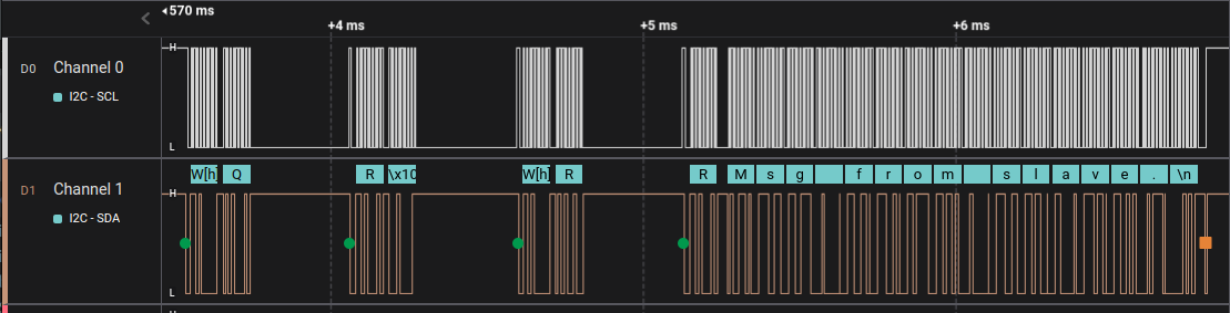
Testing
The following snapshots are taken using the Logic Analyzer.
Entire Communication
Cross-Checking using the STM32CubeIDE Console