Home | Projects | Notes > MCU Peripheral Drivers > I2C Application 4: Slave Tx (Interrupt) (i2c_04_slave_tx_interrupt.c)
I2C Application 4: Slave Tx (Interrupt) (i2c_04_slave_tx_interrupt.c)
Requirements
I2C master (Arduino board) and I2C slave (STM32 Discovery board) communication.
Master (Arduino) shall read and display data from slave (STM32) connected. First, master has to get the length information of the data to be received from the slave, and then read the data sent by the slave.
Use I2C SCL = 100 kHz (i.e., standard mode)
Use external pull-up resistors for SDA and SCL line (Internal pull-up resistors are also fine!)
[!] Note: 3.3 kΩ or 4.7 kΩ external pull-up resistors are necessary in case your MCU pins do not support internal pull-up resistors.
External Pull-Up Resistance Calculation
According to the I2C specification:
Parts Needed
Arduino board
STM32 board
Logic level converter
Breadboard and jumper wires
2 pull-up resistors of resistance 3.3 kΩ or 4.7 kΩ (You can also use internal pull-up resistors of the pins in place of external resistors.)
Q: We calculated the Rp(max) to be 3 kΩ. If 3 is the max, then why would 3.3 or 4.7 kΩ resistors work? Wouldn't these be higher resistance than the max? Is there a tolerable range? If so, how do I find this range?
A: Rp(max) refers to the maximum recommended value for the pull-up resistor. If the calculated Rp(max) is 3kOhms, it means that the manufacturer or standard recommends using a pull-up resistor with a value equal to or lower than 3kOhms for reliable operation.
However, using a resistor with a slightly higher value, such as 3.3kOhms or 4.7kOhms, is generally acceptable in practice. The bus capacitance and other factors in the system design can influence the actual pull-up resistor value that works reliably. As long as the chosen resistor value is close to the recommended range and the overall system performance is satisfactory, using 3.3kOhms or 4.7kOhms resistors should be fine.
It's important to note that selecting a pull-up resistor with a significantly higher value than Rp(max) may lead to slower rise times and increased susceptibility to noise or signal integrity issues. On the other hand, choosing a resistor with a significantly lower value may result in excessive current flow and power dissipation. Therefore, it's generally best to stay within the recommended range while considering the specific requirements and constraints of the system.
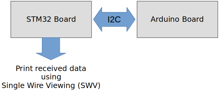
STM32 Board and Arduino Board Communication Interfaces

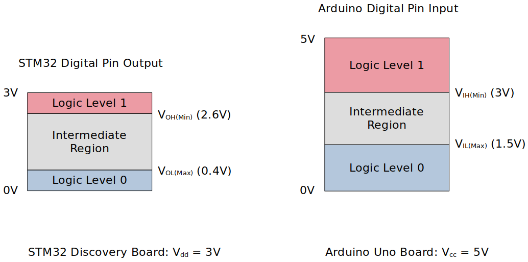
STM32 Board and Arduino Board Voltage Levels
To work around the voltage level difference, a logic level shifter will be necessary.

Procedure to Send Data to Master (Arduino) as Slave (STM32)
Master (Arduino) will control the I2C transaction. Slave (STM32) will simply react to master's commands.
Master sends command code (0x51) to fetch 1 byte of data length information from the slave.
Master sends command code (0x52) to read the complete data from the slave.
Using printf() to Print Messages in STM32CubeIDE Console
Setup
1. Find out the GPIO pins that can be used for IC2 communication
For this application, I2C communication lines SCL, SDA will be used. Find out the GPIO pins over which I2C can communicate! Look up the "Alternate function mapping" table in the datasheet.
I2C1_SCL
I2C1_SDA
Although, in the documentation, it is said that PB9 can be used as I2C1_SDA, some interference has been detected while testing due to the hardware circuitry called "SWIM" so ended up using PB7 instead.
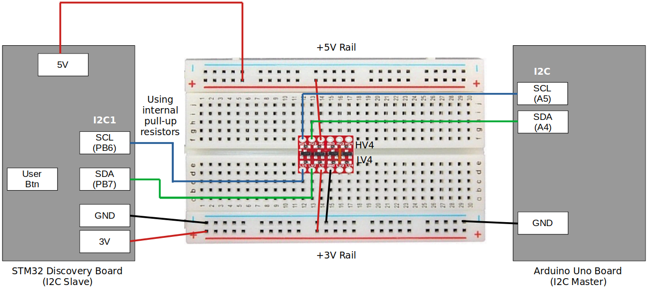
2. Connect STM32 Discovery board with Arduino Uno board I2C pins
Be careful not to directly supply 5 volts to the STM32 board pins when the board is not powered up as they may be damaged. When the logic level shifter is used, you don't need to worry about this issue.

To analyze the communication with the logic analyzer, connect the channels as follows:
CH0 - SCL
CH1 - SDA
GND - Common GND of the bread board
3. Power Arduino board and download SPI slave sketch to Arduino
Sketch name:
003I2CMasterRxString.inoYou don't need to write an application for Arduino board. It is already provided as a sketch.
As soon as you download this sketch to the Arduino board, it will operate as a master.
Code
i2c_04_slave_tx_interrupt.c
Path: Project/Src/
xxxxxxxxxx1971/*******************************************************************************2 * File : i2c_04_slave_tx_interrupt.c3 * Brief : Program to test I2C slave's Tx (interrupt) functionality4 * Author : Kyungjae Lee5 * Date : Jun 18, 20236 ******************************************************************************/7
8/**9 * Pin selection for I2C communication10 *11 * I2C1_SCL - PB6 (AF4)12 * I2C1_SDA - PB7 (AF4)13 */14
15/* strlen() */16/* printf() */17
19/* STM32 Discovery board's address */20/* In this app, STM32 board is slave */21
22/* Global variables */23I2C_Handle_TypeDef I2C1Handle;24uint8_t txBuff[32] = "Msg from STM32 slave.";25 /* Arduino wire library limits the length of I2C data to be <= 32 bytes */26
27/**28 * delay()29 * Brief : Spinlock delays the program execution30 * Param : None31 * Retval : None32 * Note : N/A33 */34void delay(void)35{36 /* Appoximately ~200ms delay when the system clock freq is 16 MHz */37 for (uint32_t i = 0; i < 500000 / 2; i++);38} /* End of delay */39
40/**41 * I2C1_PinsInit()42 * Brief : Initializes and configures GPIO pins to be used as I2C1 pins43 * Param : None44 * Retval : None45 * Note : N/A46 */47void I2C1_PinsInit(void)48{49 GPIO_Handle_TypeDef I2CPins;50
51 I2CPins.pGPIOx = GPIOB;52 I2CPins.GPIO_PinConfig.GPIO_PinMode = GPIO_PIN_MODE_ALTFCN;53 I2CPins.GPIO_PinConfig.GPIO_PinOutType = GPIO_PIN_OUT_TYPE_OD;54 I2CPins.GPIO_PinConfig.GPIO_PinPuPdControl = GPIO_PIN_PU;55 I2CPins.GPIO_PinConfig.GPIO_PinAltFcnMode = 4;56 I2CPins.GPIO_PinConfig.GPIO_PinSpeed = GPIO_PIN_OUT_SPEED_HIGH;57
58 /* SCL */59 I2CPins.GPIO_PinConfig.GPIO_PinNumber = GPIO_PIN_6;60 GPIO_Init(&I2CPins);61
62 /* SDA */63 I2CPins.GPIO_PinConfig.GPIO_PinNumber = GPIO_PIN_7;64 GPIO_Init(&I2CPins);65} /* End of I2C1_PinsInit */66
67/**68 * I2C1_Init()69 * Brief : Creates an SPI2Handle initializes SPI2 peripheral parameters70 * Param : None71 * Retval : None72 * Note : N/A73 */74void I2C1_Init(void)75{76
77 I2C1Handle.pI2Cx = I2C1;78 I2C1Handle.I2C_Config.I2C_ACKEnable = I2C_ACK_ENABLE;79 I2C1Handle.I2C_Config.I2C_DeviceAddress = MY_ADDR;80 /* Since STM32 board is master, I2C_DeviceAddress field does not have81 * to be configured. However, you can assign some dummy value to it if82 * you wanted to. When selecting the dummy address value, make sure to83 * avoid using the reserved addresses defined in the I2C specification.84 */85 I2C1Handle.I2C_Config.I2C_FMDutyCycle = I2C_FM_DUTY_2;86 I2C1Handle.I2C_Config.I2C_SCLSpeed = I2C_SCL_SPEED_SM;87
88 I2C_Init(&I2C1Handle);89} /* End of I2C1_Init */90
91
92int main(int argc, char *argv[])93{94 printf("Application Running\n");95
96 /* Initialize I2C pins */97 I2C1_PinsInit();98
99 /* Configure I2C peripheral */100 I2C1_Init();101
102 /* I2C IRQ configurations */103 I2C_IRQInterruptConfig(IRQ_NO_I2C1_EV, ENABLE);104 I2C_IRQInterruptConfig(IRQ_NO_I2C1_ER, ENABLE);105
106 I2C_SlaveEnableDisableCallbackEvents(I2C1, ENABLE);107
108 /* Enable I2C peripheral (PE bit gets set here) */109 I2C_PeriControl(I2C1, ENABLE);110
111 /* Enable ACK112 * ACK bit is set and cleared by SW, and cleared by HW when PE=0.113 * Since PE bit has just been set in the 'I2C_PeriControl()' function,114 * now you can set the ACK bit. */115 I2C_ManageACK(I2C1, ENABLE);116
117 while (1);118} /* End of main */119
120/**121 * I2C1_ER_IRQHandler()122 * Brief : Handles I2C error IRQ123 * Param : None124 * Retval : None125 * Note : This function calls 'I2C_ER_IRQHandling()' function which126 * implements the actual error IRQ handling functionality.127 */128void I2C1_ER_IRQHandler(void)129{130 I2C_ER_IRQHandling(&I2C1Handle);131} /* End of I2C1_ER_IRQHandler */132
133/**134 * I2C1_EV_IRQHandler()135 * Brief : Handles I2C event IRQ136 * Param : None137 * Retval : None138 * Note : This function calls 'I2C_EV_IRQHandling()' function which139 * implements the actual event IRQ handling functionality.140 */141void I2C1_EV_IRQHandler(void)142{143 I2C_EV_IRQHandling(&I2C1Handle);144} /* End of I2C1_EV_IRQHandler */145
146/**147 * I2C_ApplicationEventCallback()148 * Brief : Notifies the application of the event occurred149 * Param : @pSPIHandle - pointer to SPI handle structure150 * @appEvent - SPI event occurred151 * Retval : None152 * Note : Contents of this function depends on the I2C transactions used153 * in the application. (e.g., Master's write operation results in154 * slave's read.)155 */156void I2C_ApplicationEventCallback(I2C_Handle_TypeDef *pI2CHandle, uint8_t appEvent)157{158 /* Static variables are not allocated in the stack. These variables will159 * last throughout the duration of the program.160 */161 static uint8_t cmdCode = 0;162 static uint8_t cnt = 0;163
164 if (appEvent == I2C_EV_TX)165 {166 /* Master wants to read data. Slave has to send data. */167 if (cmdCode == 0x51)168 {169 /* Send the length information to the master */170 I2C_SlaveTx(pI2CHandle->pI2Cx, strlen((char *)txBuff));171 }172 else if (cmdCode == 0x52)173 {174 /* Send the contents of Tx buffer to the master */175 I2C_SlaveTx(pI2CHandle->pI2Cx, txBuff[cnt++]);176 }177 }178 else if (appEvent == I2C_EV_RX)179 {180 /* Data waits to be read by the slave. Let the slave read it */181 cmdCode = I2C_SlaveRx(pI2CHandle->pI2Cx);182 }183 else if (appEvent == I2C_ERROR_AF)184 {185 /* This happens only during the slave Tx.186 * Master has sent NACK, meaning that master has no more data to send.187 */188 cmdCode = 0xFF; /* Invalidate cmdCode */189 cnt = 0; /* Reset cnt */190 }191 else if (appEvent == I2C_EV_STOP)192 {193 /* This happens only during slave Rx.194 * Master has ended the I2C communication with the slave.195 */196 }197} /* End of I2C_ApplicationEventCallback */
Arduino Sketch (003I2CMasterRxString.ino)
xxxxxxxxxx701// Wire Master Transmitter and Receiver 2//Uno, Ethernet A4 (SDA), A5 (SCL)3
5// Include the required Wire library for I2C<br>#include <Wire.h>6int LED = 13;7
8uint8_t rcv_buf[32];9
10int data_len=0;11/* Address of STM32 Discorvery board (slave) */12
13void setup() {14 Serial.begin(9600);15 16 // Define the LED pin as Output17 pinMode (LED, OUTPUT);18 19 // join i2c bus (address optional for master)20 Wire.begin(); 21}22
23
24void loop() {25
26 Serial.println("Arduino Master");27 Serial.println("Send character \"s\" to begin");28 Serial.println("-----------------------------");29
30 while(!Serial.available());31 char in_read=Serial.read();32
33 while(in_read != 's');34
35 Serial.println("Starting..");36
37 Wire.beginTransmission(SLAVE_ADDR);38 39 Wire.write(0X51); //Send this command to read the length40 Wire.endTransmission();41
42
43 Wire.requestFrom(SLAVE_ADDR,1); // Request the transmitted two bytes from the two registers44
45 if(Wire.available()) { // 46 data_len = Wire.read(); // Reads the data 47 }48 Serial.print("Data Length:");49 Serial.println(String(data_len,DEC));50
51 Wire.beginTransmission(SLAVE_ADDR);52 53 Wire.write(0X52); //Send this command to ask data54 Wire.endTransmission();55
56 Wire.requestFrom(SLAVE_ADDR,data_len);57
58 uint32_t i=0;59 for( i =0; i <= data_len ; i++)60 {61 if(Wire.available()) { // 62 rcv_buf[i] = Wire.read(); // Reads the data 63 }64 }65 rcv_buf[i] = '\0';66
67 Serial.print("Data:");68 Serial.println((char*)rcv_buf);69 Serial.println("*********************END*********************");70}
Testing
The following snapshots are taken using the Logic Analyzer.
Entire Communication

Communication in Detail


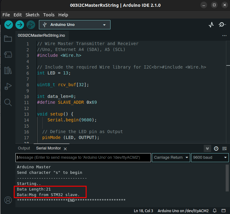
Cross-Checking using the Arduino IDE Serial Monitor Tool
