Home | Projects | Notes > MCU Peripheral Drivers > SPI Application 3: Master-Slave Tx Rx (Blocking) (spi_03_master_tx_rx_blocking.c)
SPI Application 3: Master Tx Rx (Blocking) (spi_03_master_tx_rx_blocking.c)
Requirements
SPI master(STM) and SPI slave(Arduino) command & response based communication
When the button on the master is pressed, master shall send a command to the slave and slave shall respond as per the command implementation.
Requirements
Use SPI full duplex mode
ST board will be in SPI master mode, and Arduino board will be in SPI slave mode.
Use DFF = 0
Use hardware slave management (SSM = 0)
SCLK speed = 500 KHz, fclk = 16MHz
The slave does not know how many bytes of data master is going to send. So, the master must first send the number of bytes the slave should expect to receive.
Parts Needed
Arduino board
STM32 board
Logic level converter
Breadboard and jumper wires
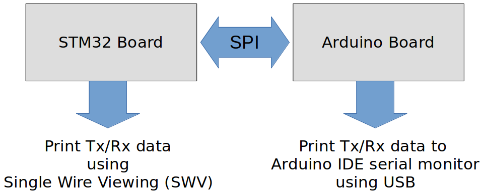
STM32 Board and Arduino Board Communication Interfaces

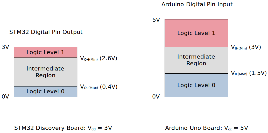
STM32 Board and Arduino Board Voltage Levels
To work around the voltage level difference, a logic level shifter will be necessary.

Master - Slave Communication
Communication sequence:
Master sends a command to slave.
Slave responds with
ACK(0xF5)orNACK(0xA5)byte.If master recieves
ACK, it sends 1 or more command arguments.Slave takes action and responds to master according to the command/arguments it has received
If master receives
NACK, it displays error message.
Command formats
Following commands are provided by the Arduino sketch
xxxxxxxxxx71<command_code(1)> <arg1> <arg2>2====================== ====================== =============3CMD_LED_CTRL <pin no(1)> <value(1)> (ON/OFF)4CMD_SENSOR_READ <analog pin number(1)>5CMD_LED_READ <pin no(1)>6CMD_PRINT <len(2)> <message(len)>7CMD_ID_READCMD_LED_CTRL <pin no> <value>is the command to turn on/off LED connected to a specific Arduino pin<pin no>- Digital pin number of the Arduino board (0 to 9) (1 byte)<value>- 1 = ON, 0 = OFF (1 byte)
Slave action: Controls the digital pin on/off
Slave returns: Nothing
CMD_SENSOR_READ <analog pin number><analog pin number>- Analog pin number of the Arduino board (A0 to A5) (1 byte)
Slave action: Slave shall read the analog value of the supplied pin
Slave returns: 1 byte of analog read value
CMD_LED_READ <pin no><pin no>- Digital pin number of the Arduino board (0 to 9)
Slave action: Reads the status of the supplied pin number
Slave returns: 1 byte of LED status (1 = ON, 0 = OFF)
CMD_PRINT <len> <message><len>- 1 byte of length information of the message to follow<message>- Message oflenbytes
Slave action: Receives the message and displays it via serial port
Slave returns: Nothing
CMD_ID_READSlave returns: 10 bytes of board ID string
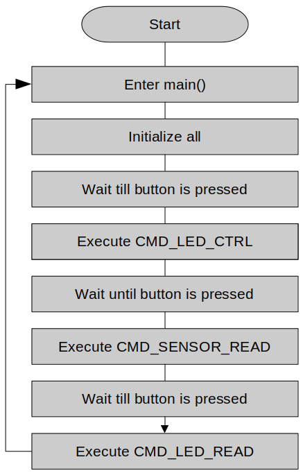
Application Flow Chart

Using printf() to Print Messages in STM32CubeIDE Console
Setup
1. Find out the GPIO pins that can be used for SPI2 communication
For this application, all four SPI communication lines (i.e., MOSI, MISO, SCK and NSS pins) will be used. Find out the GPIO pins over which SPI2 can communicate! Look up the "Alternate function mapping" table in the datasheet.
SPI2_MOSI
SPI2_SCK
SPI2_MISO
SPI2_NSS
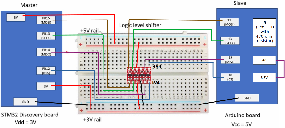
2. Connect STM32 Discovery board with Arduino Uno board SPI pins
Be careful not to directly supply 5 volts to the STM32 board pins when the board is not powered up as they may be damaged. When the logic level shifter is used, you don't need to worry about this issue.

To analyze the communication with the logic analyzer, connect the channels as follows:
CH0 - SCLK
CH1 - MOSI
CH2 - MISO
CH3 - NSS
GND - Common GND of the bread board
3. Power Arduino board and upload SPI slave sketch to Arduino
Sketch name:
002SPISlaveCmdHandling.inoAs soon as you download this sketch to the Arduino board, it will operate as a slave.
Code
spi_03_master_tx_rx_blocking.c
Path: Project/Src/
xxxxxxxxxx5641/*******************************************************************************2 * File : spi_03_master_tx_rx_blocking.c3 * Brief : Program to test SPI master-slave Tx/Rx functionality (blocking)4 * Author : Kyungjae Lee5 * Date : Jun 03, 20236 ******************************************************************************/7
8/**9 * Pin selection for SPI communication10 *11 * SPI2_SCK - PB13 (AF5)12 * SPI2_MOSI - PB15 (AF5)13 * SPI2_MISO - PB14 (AF5)14 * SPI2_NSS - PB12 (AF5)15 */16
17/* printf() */18/* strlen() */19
21/* Arduino (slave) command codes */22
28
31/* Arduino analog pin */32
38/* Arduino LED pin */39
41/**42 * delay()43 * Brief : Spinlock delays the program execution44 * Param : None45 * Retval : None46 * Note : N/A47 */48void delay(void)49{50 /* Appoximately ~200ms delay when the system clock freq is 16 MHz */51 for (uint32_t i = 0; i < 500000 / 2; i++);52} /* End of Delay */53
54/**55 * SPI2_PinsInit()56 * Brief : Initializes and configures GPIO pins to be used as SPI2 pins57 * Param : None58 * Retval : None59 * Note : N/A60 */61void SPI2_PinsInit(void)62{63 GPIO_Handle_TypeDef SPI2Pins;64
65 /* Zero-out all the fields in the structures (Very important! SPI2Pins66 * is a local variables whose members may be filled with garbage values before67 * initialization. These garbage values may set (corrupt) the bit fields that68 * you did not touch assuming that they will be 0 by default. Do NOT make this69 * mistake!70 */71 memset(&SPI2Pins, 0, sizeof(SPI2Pins));72
73 SPI2Pins.pGPIOx = GPIOB;74 SPI2Pins.GPIO_PinConfig.GPIO_PinMode = GPIO_PIN_MODE_ALTFCN;75 SPI2Pins.GPIO_PinConfig.GPIO_PinAltFcnMode = 5;76 SPI2Pins.GPIO_PinConfig.GPIO_PinOutType = GPIO_PIN_OUT_TYPE_PP;77 /* I2C - Open-drain only!, SPI - Push-pull okay! */78 SPI2Pins.GPIO_PinConfig.GPIO_PinPuPdControl = GPIO_PIN_NO_PUPD; /* Optional */79 SPI2Pins.GPIO_PinConfig.GPIO_PinSpeed = GPIO_PIN_OUT_SPEED_HIGH; /* Medium or slow ok as well */80
81 /* SCLK */82 SPI2Pins.GPIO_PinConfig.GPIO_PinNumber = GPIO_PIN_13;83 GPIO_Init(&SPI2Pins);84
85 /* MOSI */86 SPI2Pins.GPIO_PinConfig.GPIO_PinNumber = GPIO_PIN_15;87 GPIO_Init(&SPI2Pins);88
89 /* MISO */90 SPI2Pins.GPIO_PinConfig.GPIO_PinNumber = GPIO_PIN_14;91 GPIO_Init(&SPI2Pins);92
93 /* NSS */94 SPI2Pins.GPIO_PinConfig.GPIO_PinNumber = GPIO_PIN_12;95 GPIO_Init(&SPI2Pins);96} /* End of SPI2_PinsInit */97
98/**99 * SPI2_Init()100 * Brief : Creates an SPI2Handle and initializes SPI2 peripheral parameters101 * Param : None102 * Retval : None103 * Note : N/A104 */105void SPI2_Init(void)106{107 SPI_Handle_TypeDef SPI2Handle;108
109 /* Zero-out all the fields in the structures (Very important! SPI2Handle110 * is a local variables whose members may be filled with garbage values before111 * initialization. These garbage values may set (corrupt) the bit fields that112 * you did not touch assuming that they will be 0 by default. Do NOT make this113 * mistake!114 */115 memset(&SPI2Handle, 0, sizeof(SPI2Handle));116
117 SPI2Handle.pSPIx = SPI2;118 SPI2Handle.SPI_Config.SPI_BusConfig = SPI_BUS_CONFIG_FULL_DUPLEX;119 SPI2Handle.SPI_Config.SPI_DeviceMode = SPI_DEVICE_MODE_MASTER;120 SPI2Handle.SPI_Config.SPI_SCLKSpeed = SPI_SCLK_SPEED_PRESCALAR_32; /* Generates 500KHz SCLK */121 /* Min prescalar -> maximum clk speed */122 SPI2Handle.SPI_Config.SPI_DFF = SPI_DFF_8BITS;123 SPI2Handle.SPI_Config.SPI_CPOL = SPI_CPOL_LOW;124 SPI2Handle.SPI_Config.SPI_CPHA = SPI_CPHA_LOW;125 SPI2Handle.SPI_Config.SPI_SSM = SPI_SSM_DI; /* HW slave mgmt enabled (SSM = 0) for NSS pin */126
127 SPI_Init(&SPI2Handle);128} /* End of SPI2_Init */129
130/**131 * GPIO_ButtonInit()132 * Brief : Initializes a GPIO pin for button133 * Param : None134 * Retval : None135 * Note : N/A136 */137void GPIO_ButtonInit(void)138{139 GPIO_Handle_TypeDef GPIOBtn;140
141 /* Zero-out all the fields in the structures (Very important! GPIOLed and GPIOBtn142 * is a local variables whose members may be filled with garbage values before143 * initialization. These garbage values may set (corrupt) the bit fields that144 * you did not touch assuming that they will be 0 by default. Do NOT make this145 * mistake!146 */147 memset(&GPIOBtn, 0, sizeof(GPIOBtn));148
149 /* GPIOBtn configuration */150 GPIOBtn.pGPIOx = GPIOA;151 GPIOBtn.GPIO_PinConfig.GPIO_PinNumber = GPIO_PIN_0;152 GPIOBtn.GPIO_PinConfig.GPIO_PinMode = GPIO_PIN_MODE_IN;153 GPIOBtn.GPIO_PinConfig.GPIO_PinSpeed = GPIO_PIN_OUT_SPEED_HIGH; /* Doesn't matter */154 //GPIOBtn.GPIO_PinConfig.GPIO_PinOutType = GPIO_PIN_OUT_TYPE_PP; /* N/A */155 GPIOBtn.GPIO_PinConfig.GPIO_PinPuPdControl = GPIO_PIN_NO_PUPD;156 /* External pull-down resistor is already present (see the schematic) */157 GPIO_Init(&GPIOBtn);158} /* End of GPIO_ButtonInit */159
160/**161 * GPIO_LEDInit()162 * Brief : Initializes a GPIO pin for LED163 * Param : None164 * Retval : None165 * Note : N/A166 */167void GPIO_LEDInit(void)168{169 GPIO_Handle_TypeDef GPIOLed;170
171 /* Zero-out all the fields in the structures (Very important! GPIOLed172 * is a local variable whose members may be filled with garbage values before173 * initialization. These garbage values may set (corrupt) the bit fields that174 * you did not touch assuming that they will be 0 by default. Do NOT make this175 * mistake!176 */177 memset(&GPIOLed, 0, sizeof(GPIOLed));178
179 /* GPIOLed configuration */180 GPIOLed.pGPIOx = GPIOD;181 GPIOLed.GPIO_PinConfig.GPIO_PinNumber = GPIO_PIN_12;182 GPIOLed.GPIO_PinConfig.GPIO_PinMode = GPIO_PIN_MODE_OUT;183 GPIOLed.GPIO_PinConfig.GPIO_PinSpeed = GPIO_PIN_OUT_SPEED_HIGH; /* Doesn't matter */184 GPIOLed.GPIO_PinConfig.GPIO_PinOutType = GPIO_PIN_OUT_TYPE_OD;185 GPIOLed.GPIO_PinConfig.GPIO_PinPuPdControl = GPIO_PIN_NO_PUPD;186 /* External pull-down resistor is already present (see the schematic) */187 GPIO_Init(&GPIOLed);188} /* End of GPIO_LEDInit */189
190/**191 * SPI_VerifyResponse()192 * Brief : Verifies response from the slave (Arduino)193 * Param : @ackByte - response from slave194 * Retval : 1 if response was ACK, 0 otherwise195 * Note : N/A196 */197uint8_t SPI_VerifyResponse(uint8_t ackByte)198{199 /* ACK */200 if (ackByte == 0xF5)201 return 1;202 /* NACK */203 else204 return 0;205} /* End of SPI_VerifyResponse */206
207
208int main(int argc, char *argv[])209{210 uint8_t dummyWrite = 0xFF;211 uint8_t dummyRead;212
213 printf("Application is running...\n");214
215 /* Initialize and configure GPIO pin for user button */216 GPIO_ButtonInit();217
218 /* Initialize and configure GPIO pin for LED */219 GPIO_LEDInit();220
221 /* Initialize and configure GPIO pins to be used as SPI2 pins */222 SPI2_PinsInit();223
224 /* Initialize SPI2 peripheral parameters */225 SPI2_Init();226 /* At this point, all the required parameters are loaded into SPIx control registers.227 * But, this does not mean that SPI2 peripheral is enabled.228 *229 * SPI configuration must be completed before it is enabled. When SPI is enabled, it230 * will be busy communicating with other device(s) and will not allow modifying its231 * control registers.232 */233
234 printf("SPI initialized\n");235
236 /* Enable NSS output (Set SPI_CR2 bit[2] SSOE - Slave Select Output Enable) */237 SPI_SSOEConfig(SPI2, ENABLE);238 /* Setting SSOE bit to 1 enables the NSS output.239 * The NSS pin is automatically managed by the hardware.240 * i.e., When SPE = 1, NSS will be pulled to low, and when SPE = 0, NSS will be241 * pulled to high.242 */243
244 while (1)245 {246 /* Wait until button is pressed */247 while (!GPIO_ReadFromInputPin(GPIOA, GPIO_PIN_0));248
249 /* Introduce debouncing time for button press */250 delay();251
252 /* Enable SPI2 peripheral (Set SPI_CR1 bit[6] SPE - Peripheral enabled) */253 SPI_PeriControl(SPI2, ENABLE);254
255 /* 1. CMD_LED_CTRL <pin no(1)> <value(1)> ----------------------------*/256
257 uint8_t cmdCode = CMD_LED_CTRL;258 uint8_t ackByte;259 uint8_t args[2];260
261 /* Send command */262 SPI_TxBlocking(SPI2, &cmdCode, 1);263 /* Remember! In SPI communication, when master or slave sends 1 byte of data264 * it also receives 1 byte in return.265 *266 * This transmission of 1 byte results in 1 garbage byte collection in267 * Rx buffer of the master and therefore RXNE flag will be set. So, do the268 * dummy read and clear the flag.269 */270
271 /* Dummy read to clear the RXNE bit */272 SPI_RxBlocking(SPI2, &dummyRead, 1);273
274 /* Send a dummy byte (or 2 bytes if 16-bit DFF) to fetch the response from the slave.275 * (To init the communication)276 */277 SPI_TxBlocking(SPI2, &dummyWrite, 1);278 /* When this API call returns, response from the slave would've arrived at279 * the master. So, let's read next.280 */281
282 /* Read the ACK byte received */283 SPI_RxBlocking(SPI2, &ackByte, 1);284
285 if (SPI_VerifyResponse(ackByte))286 {287 /* Compose arguments */288 args[0] = LED_PIN;289 args[1] = LED_ON;290
291 /* Send arguments */292 SPI_TxBlocking(SPI2, args, 2);293
294 printf("CMD_LED_CTRL executed\n");295 }296 /* End of CMD_LED_CTRL */297
298 /* 2. CMD_SENSOR_READ <analog pin number(1)> -------------------------*/299
300 /* Wait until button is pressed */301 while (!GPIO_ReadFromInputPin(GPIOA, GPIO_PIN_0));302
303 /* Introduce debouncing time for button press */304 delay();305
306 cmdCode = CMD_SENSOR_READ;307
308 /* Send command */309 SPI_TxBlocking(SPI2, &cmdCode, 1);310 /* Remember! In SPI communication, when master or slave sends 1 byte of data311 * it also receives 1 byte in return.312 *313 * This transmission of 1 byte results in 1 garbage byte collection in314 * Rx buffer of the master and therefore RXNE flag will be set. So, do the315 * dummy read and clear the flag.316 */317
318 /* Dummy read to clear the RXNE bit */319 SPI_RxBlocking(SPI2, &dummyRead, 1);320
321 /* Send a dummy byte (or 2 bytes if 16-bit DFF) to fetch the response from the slave.322 * (To init the communication)323 */324 SPI_TxBlocking(SPI2, &dummyWrite, 1);325 /* When this API call returns, response from the slave would've arrived at326 * the master. So, let's read next.327 */328
329 /* Read the ACK byte received */330 SPI_RxBlocking(SPI2, &ackByte, 1);331
332 if (SPI_VerifyResponse(ackByte))333 {334 /* Compose arguments */335 args[0] = ANALOG_PIN0;336
337 /* Send arguments */338 SPI_TxBlocking(SPI2, args, 1);339
340
341 /* Dummy read to clear the RXNE bit */342 SPI_RxBlocking(SPI2, &dummyRead, 1);343
344 /* Introduce delay to give slave enough time to do ADC conversion345 * (Master should wait before generating the dummy bits to fetch346 * the result.)347 */348 delay();349
350 /* Send a dummy byte (or 2 bytes if 16-bit DFF) to fetch the response from the slave.351 * (To init the communication)352 */353 SPI_TxBlocking(SPI2, &dummyWrite, 1);354 /* When this API call returns, response from the slave would've arrived at355 * the master. So, let's read next.356 */357
358 /* Read sensor data */359 uint8_t analogData;360 SPI_RxBlocking(SPI2, &analogData, 1);361 /* Analog data ranges from 0(0V) to 255(5V) */362
363 printf("CMD_SENSOR_READ: %d\n", analogData);364 }365 /* End of CMD_SENSOR_READ */366
367 /* 3. CMD_LED_READ <pin no(1)> ---------------------------------------*/368
369 /* Wait until button is pressed */370 while (!GPIO_ReadFromInputPin(GPIOA, GPIO_PIN_0));371
372 /* Introduce debouncing time for button press */373 delay();374
375 cmdCode = CMD_LED_READ;376
377 /* Send command */378 SPI_TxBlocking(SPI2, &cmdCode, 1);379 /* Remember! In SPI communication, when master or slave sends 1 byte of data380 * it also receives 1 byte in return.381 *382 * This transmission of 1 byte results in 1 garbage byte collection in383 * Rx buffer of the master and therefore RXNE flag will be set. So, do the384 * dummy read and clear the flag.385 */386
387 /* Dummy read to clear the RXNE bit */388 SPI_RxBlocking(SPI2, &dummyRead, 1);389
390 /* Send a dummy byte (or 2 bytes if 16-bit DFF) to fetch the response from the slave.391 * (To init the communication)392 */393 SPI_TxBlocking(SPI2, &dummyWrite, 1);394 /* When this API call returns, response from the slave would've arrived at395 * the master. So, let's read next.396 */397
398 /* Read the ACK byte received */399 SPI_RxBlocking(SPI2, &ackByte, 1);400
401 if (SPI_VerifyResponse(ackByte))402 {403 /* Compose arguments */404 args[0] = LED_PIN;405
406 /* Send arguments */407 SPI_TxBlocking(SPI2, args, 1);408
409
410 /* Dummy read to clear the RXNE bit */411 SPI_RxBlocking(SPI2, &dummyRead, 1);412
413 /* Introduce delay to give slave enough time to do ADC conversion414 * (Master should wait before generating the dummy bits to fetch415 * the result.)416 */417 delay();418
419 /* Send a dummy byte (or 2 bytes if 16-bit DFF) to fetch the response from the slave.420 * (To init the communication)421 */422 SPI_TxBlocking(SPI2, &dummyWrite, 1);423 /* When this API call returns, response from the slave would've arrived at424 * the master. So, let's read next.425 */426
427 uint8_t ledStatus;428 SPI_RxBlocking(SPI2, &ledStatus, 1);429
430 printf("CMD_LED_READ: %d\n", ledStatus);431 }432 /* End of CMD_LED_READ */433
434 /* 4. CMD_PRINT <len(2)> <message(len)> ------------------------------*/435
436 /* Wait until button is pressed */437 while (!GPIO_ReadFromInputPin(GPIOA, GPIO_PIN_0));438
439 /* Introduce debouncing time for button press */440 delay();441
442 cmdCode = CMD_PRINT;443
444 /* Send command */445 SPI_TxBlocking(SPI2, &cmdCode, 1);446 /* Remember! In SPI communication, when master or slave sends 1 byte of data447 * it also receives 1 byte in return.448 *449 * This transmission of 1 byte results in 1 garbage byte collection in450 * Rx buffer of the master and therefore RXNE flag will be set. So, do the451 * dummy read and clear the flag.452 */453
454 /* Dummy read to clear the RXNE bit */455 SPI_RxBlocking(SPI2, &dummyRead, 1);456
457 /* Send a dummy byte (or 2 bytes if 16-bit DFF) to fetch the response from the slave.458 * (To init the communication)459 */460 SPI_TxBlocking(SPI2, &dummyWrite, 1);461 /* When this API call returns, response from the slave would've arrived at462 * the master. So, let's read next.463 */464
465 /* Read the ACK byte received */466 SPI_RxBlocking(SPI2, &ackByte, 1);467
468 uint8_t message[] = "Hello, how are you?";469 if (SPI_VerifyResponse(ackByte))470 {471 /* Compose arguments */472 args[0] = strlen((char *)message);473
474 /* Send arguments */475 SPI_TxBlocking(SPI2, args, 1); /* Sending length */476
477 /* Dummy read to clear the RXNE bit */478 SPI_RxBlocking(SPI2, &dummyRead, 1);479
480 /* Introduce delay to give slave enough time to do ADC conversion481 * (Master should wait before generating the dummy bits to fetch482 * the result.)483 */484 delay();485
486 /* Send message */487 for (int i = 0; i < args[0]; i++)488 {489 SPI_TxBlocking(SPI2, &message[i], 1);490 SPI_RxBlocking(SPI2, &dummyRead, 1);491 }492
493 printf("CMD_PRINT executed\n");494 }495 /* End of CMD_PRINT */496
497 /* 5. CMD_ID_READ ----------------------------------------------------*/498
499 /* Wait until button is pressed */500 while (!GPIO_ReadFromInputPin(GPIOA, GPIO_PIN_0));501
502 /* Introduce debouncing time for button press */503 delay();504
505 cmdCode = CMD_PRINT;506
507 /* Send command */508 SPI_TxBlocking(SPI2, &cmdCode, 1);509 /* Remember! In SPI communication, when master or slave sends 1 byte of data510 * it also receives 1 byte in return.511 *512 * This transmission of 1 byte results in 1 garbage byte collection in513 * Rx buffer of the master and therefore RXNE flag will be set. So, do the514 * dummy read and clear the flag.515 */516
517 /* Dummy read to clear the RXNE bit */518 SPI_RxBlocking(SPI2, &dummyRead, 1);519
520 /* Send a dummy byte (or 2 bytes if 16-bit DFF) to fetch the response from the slave.521 * (To init the communication)522 */523 SPI_TxBlocking(SPI2, &dummyWrite, 1);524 /* When this API call returns, response from the slave would've arrived at525 * the master. So, let's read next.526 */527
528 /* Read the ACK byte received */529 SPI_RxBlocking(SPI2, &ackByte, 1);530
531 uint8_t id[11];532 uint32_t i = 0;533 if (SPI_VerifyResponse(ackByte))534 {535 /* Read 10 bytes ID from the slave */536 for (i = 0; i < 10; i++)537 {538 /* Send dummy byte to fetch data from slave */539 SPI_TxBlocking(SPI2, &dummyWrite, 1);540 SPI_RxBlocking(SPI2, &id[i], 1);541 }542
543 id[10] = '\0';544
545 printf("CMD_ID: %s\n", id);546 }547 /* End of CMD_ID_READ */548
549 /* Wait until SPI no longer busy */550 while (SPI2->SR & (0x1 << SPI_SR_BSY));551 /* SPI_SR bit[7] - BSY (Busy flag)552 * 0: SPI (or I2S) not busy553 * 1: SPI (or I2S) is busy in communication or Tx buffer is not empty554 * This flag is set and cleared by hardware.555 */556
557 /* Disable SPI2 peripheral (Terminate communication) */558 SPI_PeriControl(SPI2, DISABLE);559
560 printf("SPI communication closed.\n");561 }562
563 return 0;564} /* End of main */The master's clock frequency has been adjusted from 2 MHz (prescalar = 8) to 500 KHz (prescalar = 32) to be compatible with the baudrate (1200) of the slave.
Arduino Sketch (002SPISlaveCmdHandling.ino)
xxxxxxxxxx1771/*2
3 * SPI pin numbers:4 * SCK 13 // Serial Clock.5 * MISO 12 // Master In Slave Out.6 * MOSI 11 // Master Out Slave In.7 * SS 10 // Slave Select8 *9
10 */11
12
14const byte led = 9; // Slave LED digital I/O pin.15boolean ledState = HIGH; // LED state flag.16uint8_t dataBuff[255];17uint8_t board_id[10] = "ARDUINOUNO";18
19
22//command codes23
29
32//arduino analog pins33
39//Initialize SPI slave.40void SPI_SlaveInit(void) 41{ 42 // Initialize SPI pins.43 pinMode(SCK, INPUT);44 pinMode(MOSI, INPUT);45 pinMode(MISO, OUTPUT);46 pinMode(SS, INPUT);47 //make SPI as slave48 49 // Enable SPI as slave.50 SPCR = (1 << SPE);51}52
53//This function returns SPDR Contents 54uint8_t SPI_SlaveReceive(void)55{56 /* Wait for reception complete */57 while(!(SPSR & (1<<SPIF)));58 /* Return Data Register */59 return SPDR;60}61
62
63//sends one byte of data 64void SPI_SlaveTransmit(uint8_t data)65{66 /* Start transmission */67 SPDR = data;68 69 /* Wait for transmission complete */70 while(!(SPSR & (1<<SPIF)));71}72 73
74// The setup() function runs after reset.75void setup() 76{77 // Initialize serial for troubleshooting.78 Serial.begin(1200);79 80 // Initialize slave LED pin.81 pinMode(led, OUTPUT);82 83 digitalWrite(led,LOW);84 85 // Initialize SPI Slave.86 SPI_SlaveInit();87 88 Serial.println("Slave Initialized");89}90
91
92byte checkData(byte commnad)93{94 //todo95 return ACK;96}97
98// The loop function runs continuously after setup().99void loop() 100{101 byte data,command,len,ackornack=NACK;102 103 //1. fist make sure that ss is low . so lets wait until ss is low 104 Serial.println("Slave waiting for ss to go low");105 while(digitalRead(SS) );106 107 //2. now lets wait until rx buffer has a byte108 command = SPI_SlaveReceive();109 ackornack = checkData(command);110 111 SPI_SlaveTransmit(ackornack);112 113 len = SPI_SlaveReceive(); //dummy byte114 115 if(command == COMMAND_LED_CTRL)116 {117 //read 2 more bytes pin number and value 118 uint8_t pin = SPI_SlaveReceive(); 119 uint8_t value = SPI_SlaveReceive(); 120 Serial.println("RCVD:COMMAND_LED_CTRL");121 if(value == (uint8_t)LED_ON)122 {123 digitalWrite(pin,HIGH);124 }else if (value == (uint8_t) LED_OFF)125 {126 digitalWrite(pin,LOW);127 }128 129 }else if ( command == COMMAND_SENSOR_READ)130 {131 //read analog pin number 132 uint16_t aread;133 uint8_t pin = SPI_SlaveReceive(); 134 //pinMode(pin+14, INPUT_PULLUP);135 uint8_t val;136 aread = analogRead(pin+14);137 val = map(aread, 0, 1023, 0, 255);138 139 SPI_SlaveTransmit(val);140 141 val = SPI_SlaveReceive(); //dummy read142 143 Serial.println("RCVD:COMMAND_SENSOR_READ");144 145 146 147 }else if ( command == COMMAND_LED_READ)148 {149 uint8_t pin = SPI_SlaveReceive(); 150 uint8_t val = digitalRead(pin);151 SPI_SlaveTransmit(val);152 val = SPI_SlaveReceive(); //dummy read153 Serial.println("RCVD:COMMAND_LED_READ");154 155 }else if ( command == COMMAND_PRINT)156 {157 uint8_t len = SPI_SlaveReceive(); 158 for(int i=0 ; i < len ; i++)159 {160 dataBuff[i] = SPI_SlaveReceive();161 }162 Serial.println((char*)dataBuff);163 164 Serial.println("RCVD:COMMAND_PRINT");165 166 }else if ( command == COMMAND_ID_READ)167 {168 for(int i=0 ; i < strlen(board_id) ; i++)169 {170 SPI_SlaveTransmit(board_id[i]);171 }172 SPI_SlaveReceive();173 Serial.println("RCVD:COMMAND_ID_READ");174 }175 176
177}Original baudrate (9600) has been changed to 1200 since the communication didn't work with the original baudrate. (In the STM32 application, the master's clock frequency has been adjusted from 2 MHz to 500 KHz accordingly.)
Testing
디버깅 필요! 디버거 모드로 한 줄 한 줄 실행 시 양쪽 콘솔에서 메시지들 정상 출력. 그냥 run 시 ackByte에 slave의 ACK 값이 정상적으로 저장되지 않아 일부 항목 건너 뛰는 문제가 있음.