Home | Projects | Notes > MCU Peripheral Drivers > USART Application 1: Tx (Blocking) (usart_01_tx_blocking.c)
USART Application 1: Tx (Blocking) (usart_01_tx_blocking.c)
Requirements
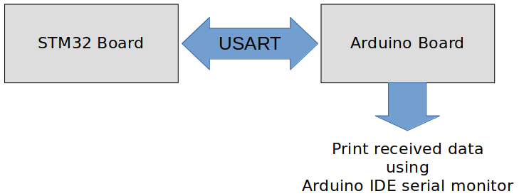
USART communication between STM32 Discovery board and Arduino Uno board.
Write a program to send some message over USART from STM32 board to Arduino board. The Arduino board will display the message sent from the STM32 board on the Arduino IDE serial monitor
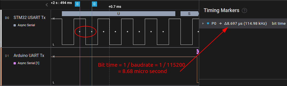
Baudrate - 115200 bps
Frame format - 1 stop bit, 8-bit user data, no parity
Parts Needed
Arduino board
STM32 board
Logic level converter
Breadboard and jumper wires
STM32 Board and Arduino Board Communication Interfaces
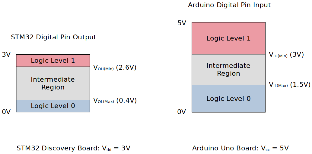
STM32 Board and Arduino Board Voltage Levels
To work around the voltage level difference, a logic level shifter will be necessary.
Using printf() to Print Messages in STM32CubeIDE Console
Setup
1. Find out the GPIO pins that can be used for USART communication
For this application, USART communication lines Tx, Rx will be used. Find out the GPIO pins over which USART can communicate! Look up the "Alternate function mapping" table in the datasheet.
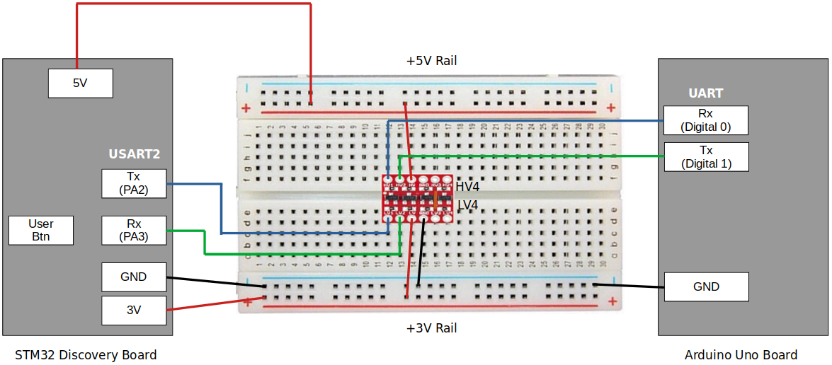
USART2_TX
USART2_RX
2. Connect STM32 Discovery board with Arduino Uno board I2C pins
Be careful not to directly supply 5 volts to the STM32 board pins when the board is not powered up as they may be damaged. When the logic level shifter is used, you don't need to worry about this issue.
To analyze the communication with the logic analyzer, connect the channels as follows:
CH0 - STM32 USART Tx
CH1 - STM32 USART Rx
GND - Common GND of the bread board
3. Power Arduino board and upload SPI slave sketch to Arduino
Sketch name:
001UARTRxString.inoYou don't need to write an application for Arduino board. It is already provided as a sketch.
As soon as you upload this sketch to the Arduino board, it will operate as a UART counterpart.
If you face an issue while uploading the sketch to the Arduino board, simply remove the Rx line, upload the sketch again and connect back the Rx line.
Code
usart_01_tx_blocking.c
Path: Project/Src/
xxxxxxxxxx1511/*******************************************************************************2 * File : usart_01_tx_blocking.c3 * Brief : Program to test USART Tx (blocking-based) functionality4 * Author : Kyungjae Lee5 * Date : Jun 20, 20236 ******************************************************************************/7
8/**9 * Pin selection for USART communication10 *11 * USART_TX - PA2 (AF7)12 * USART_RX - PA3 (AF7)13 */14
15/* strlen() */16/* printf() */17
19/* Global variables */20char msg[1024] = "USART Tx msg from STM32.\n\r";21USART_Handle_TypeDef USART2Handle;22
23/**24 * delay()25 * Brief : Spinlock delays the program execution26 * Param : None27 * Retval : None28 * Note : N/A29 */30void delay(void)31{32 /* Appoximately ~200ms delay when the system clock freq is 16 MHz */33 for (uint32_t i = 0; i < 500000 / 2; i++);34} /* End of delay */35
36/**37 * USART2_PinsInit()38 * Brief : Initializes and configures GPIO pins to be used as USART2 pins39 * Param : None40 * Retval : None41 * Note : N/A42 */43void USART2_PinsInit(void)44{45 GPIO_Handle_TypeDef USART2Pins;46
47 /* Zero-out all the fields in the structures (Very important! USASRT2Pins48 * is a local variables whose members may be filled with garbage values before49 * initialization. These garbage values may set (corrupt) the bit fields that50 * you did not touch assuming that they will be 0 by default. Do NOT make this51 * mistake!52 */53 memset(&USART2Pins, 0, sizeof(USART2Pins));54
55 USART2Pins.pGPIOx = GPIOA;56 USART2Pins.GPIO_PinConfig.GPIO_PinMode = GPIO_PIN_MODE_ALTFCN;57 USART2Pins.GPIO_PinConfig.GPIO_PinOutType = GPIO_PIN_OUT_TYPE_PP;58 USART2Pins.GPIO_PinConfig.GPIO_PinPuPdControl = GPIO_PIN_PU;59 USART2Pins.GPIO_PinConfig.GPIO_PinAltFcnMode = 7;60 USART2Pins.GPIO_PinConfig.GPIO_PinSpeed = GPIO_PIN_OUT_SPEED_HIGH;61
62 /* Tx */63 USART2Pins.GPIO_PinConfig.GPIO_PinNumber = GPIO_PIN_2;64 GPIO_Init(&USART2Pins);65
66 /* Rx */67 USART2Pins.GPIO_PinConfig.GPIO_PinNumber = GPIO_PIN_3;68 GPIO_Init(&USART2Pins);69} /* End of USART2_PinsInit */70
71/**72 * USART2_Init()73 * Brief : Initializes USART2 handle74 * Param : None75 * Retval : None76 * Note : N/A77 */78void USART2_Init(void)79{80 USART2Handle.pUSARTx = USART2;81 USART2Handle.USART_Config.USART_Baud = USART_STD_BAUD_115200;82 USART2Handle.USART_Config.USART_HWFlowControl = USART_HW_FLOW_CTRL_NONE;83 USART2Handle.USART_Config.USART_Mode = USART_MODE_TX;84 USART2Handle.USART_Config.USART_NumOfStopBits = USART_STOPBITS_1;85 USART2Handle.USART_Config.USART_WordLength = USART_WORDLEN_8BITS;86 USART2Handle.USART_Config.USART_ParityControl = USART_PARITY_DISABLE;87
88 USART_Init(&USART2Handle);89} /* End of USART2_Init */90
91/**92 * GPIO_ButtonInit()93 * Brief : Initializes a GPIO pin for button94 * Param : None95 * Retval : None96 * Note : N/A97 */98void GPIO_ButtonInit(void)99{100 GPIO_Handle_TypeDef GPIOBtn;101
102 /* Zero-out all the fields in the structures (Very important! GPIOBtn103 * is a local variables whose members may be filled with garbage values before104 * initialization. These garbage values may set (corrupt) the bit fields that105 * you did not touch assuming that they will be 0 by default. Do NOT make this106 * mistake!107 */108 memset(&GPIOBtn, 0, sizeof(GPIOBtn));109
110 /* GPIOBtn configuration */111 GPIOBtn.pGPIOx = GPIOA;112 GPIOBtn.GPIO_PinConfig.GPIO_PinNumber = GPIO_PIN_0;113 GPIOBtn.GPIO_PinConfig.GPIO_PinMode = GPIO_PIN_MODE_IN;114 GPIOBtn.GPIO_PinConfig.GPIO_PinSpeed = GPIO_PIN_OUT_SPEED_HIGH; /* Doesn't matter */115 //GPIOBtn.GPIO_PinConfig.GPIO_PinOutType = GPIO_PIN_OUT_TYPE_PP; /* N/A */116 GPIOBtn.GPIO_PinConfig.GPIO_PinPuPdControl = GPIO_PIN_NO_PUPD;117 /* External pull-down resistor is already present (see the schematic) */118 GPIO_Init(&GPIOBtn);119} /* End of GPIO_ButtonInit */120
121
122int main(int argc, char *argv[])123{124 printf("Application Running\n");125
126 /* Initialize GPIO pin for button */127 GPIO_ButtonInit();128
129 /* Initialize USART2 pins */130 USART2_PinsInit();131
132 /* Initialize USART2 peripheral */133 USART2_Init();134
135 /* Enable USART2 peripheral */136 USART_PeriControl(USART2, ENABLE);137
138 while (1)139 {140 /* Wait until button is pressed */141 while (!GPIO_ReadFromInputPin(GPIOA, GPIO_PIN_0));142
143 /* Introduce debouncing time for button press */144 delay();145
146 /* Perform data transmission */147 USART_TxBlocking(&USART2Handle, (uint8_t *)msg, strlen(msg));148 }149
150 return 0;151} /* End of main */
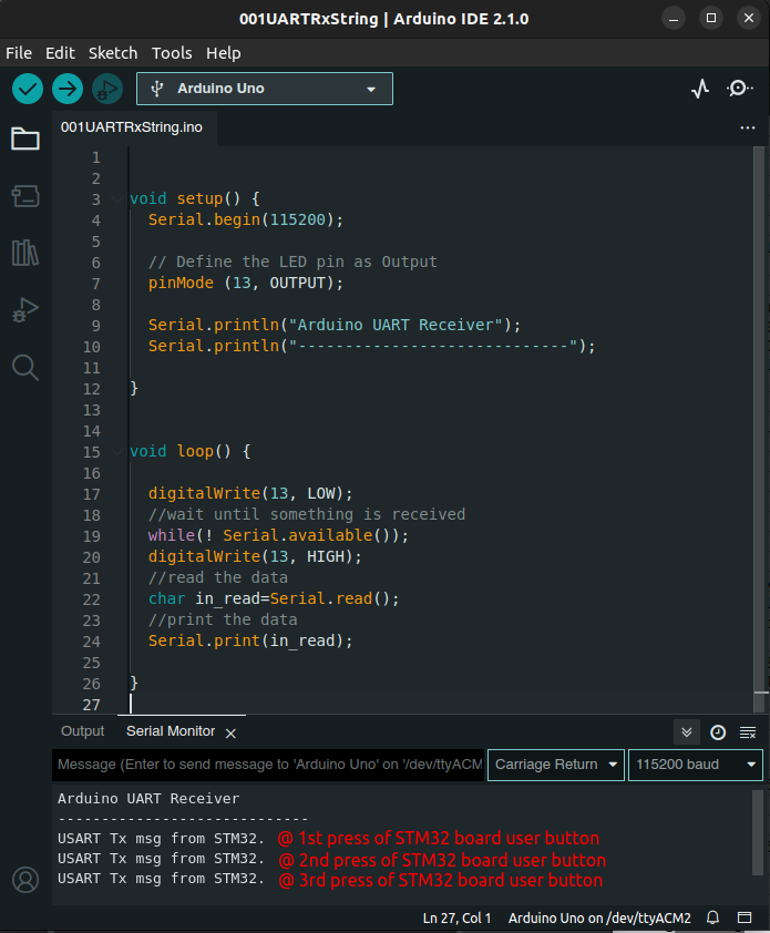
Arduino Sketch (001UARTRxString.ino)
xxxxxxxxxx211void setup() {2  Serial.begin(115200);3  4  // Define the LED pin as Output5  pinMode (13, OUTPUT);6  7  Serial.println("Arduino UART Receiver");8  Serial.println("-----------------------------"); 9}10
11void loop() {12
13  digitalWrite(13, LOW); 14  //wait until something is received15  while(! Serial.available());16  digitalWrite(13, HIGH); 17  //read the data18  char in_read=Serial.read();19  //print the data20  Serial.print(in_read);21}
Testing
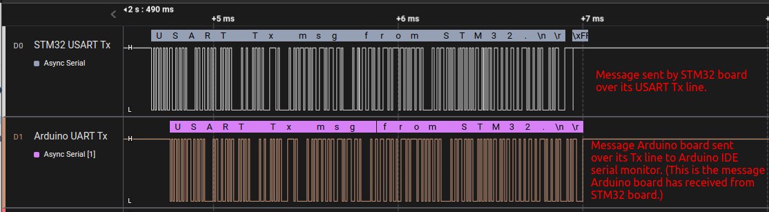
The following snapshots are taken using the Logic Analyzer.
Entire Communication
Bit Time
START / STOP Bits

Arduino IDE Serial Monitor